A special drawing frame for geological exploration

A technology of geological exploration and drawing stand, which is applied in the direction of drawing tables, applications, household appliances, etc., can solve the problems of inconvenient portability, large size, and difficulty in drawing work, and achieve the effect of easy portability and convenience

Active Publication Date: 2022-05-06
周永生
View PDF15 Cites 0 Cited by
  • Summary
  • Abstract
  • Description
  • Claims
  • Application Information

AI Technical Summary

Problems solved by technology

When carrying out geological exploration, it is often necessary to draw an exploration map, and geological exploration is often carried out in the field, so it is often necessary to use a drawing frame when drawing. It is not convenient for relevant personnel to carry it during exploration. At the same time, due to the lack of light source in field conditions, it will bring certain difficulties to the drawing work when the light is not good. A special drawing stand for geological exploration is proposed to solve the above problems.

Method used


Image

  • A special drawing frame for geological exploration
  • A special drawing frame for geological exploration
  • A special drawing frame for geological exploration

Examples


Embodiment 1

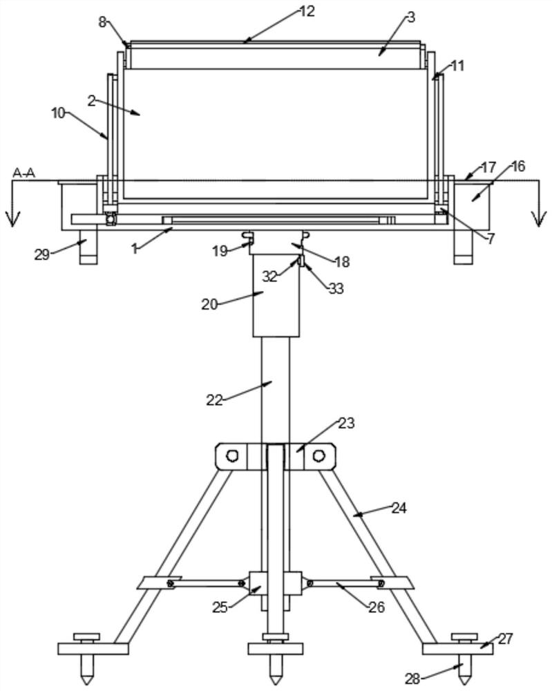
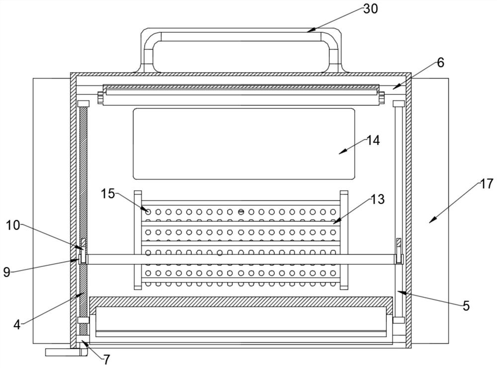
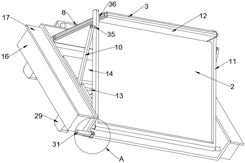
[0024] see Figure 1~5 , in an embodiment of the present invention, a special drawing frame for geological exploration, including a frame body 1, a No. 1 turret body 11 and a No. 2 turret body 12. Above the support mechanism, there is a folding lighting mechanism that drives the No. 1 turret body 11 and the No. 2 turret body 12 to move. The folding lighting mechanism includes a screw rod 4 and a No. 1 connecting rod 10. The two inner walls are provided with No. 1 fixed rod 6 and No. 2 fixed rod 7 which are fixedly connected thereto. One end of the No. 2 turret body 12 and No. 1 turret body 11 is respectively rotatably mounted on the No. 1 fixed rod 6. And on the No. 2 fixed rod 7, the No. 2 turret body 12 is provided with a solar panel 3 and the No. 1 turret body 11 is provided with a light-transmitting plate 2. Both sides of the No. 2 turret body 12 The walls are provided with guide rods 8 fixedly connected thereto, and the screw rod 4 is rotatably mounted on the inner side ...

Embodiment 2

[0032] see figure 1 The difference between this embodiment of the present invention and Embodiment 1 is that the lower ends of the plurality of No. 2 connecting rods 26 are provided with fixed seats 27 fixedly connected thereto, and the fixed seats 27 are provided with The threaded fixing cone 28, when drawing on uneven places, can fix the whole device by rotating multiple fixing cones 28 to make the whole device more stable.

[0033] The working principle of the invention is: when the whole device is fixed, multiple No. 1 connecting shaft bodies 21 can be slid into a plurality of guide connecting grooves 19 respectively, and then the turret body 1 makes the side of the No. 1 connecting shaft body 21 The wall is in contact with the inner side wall of the upper end of the guide connection groove 19 and the frame body 1 is installed on the upper end of the connecting sleeve 20, then a plurality of legs 24 are rotated by sliding the sliding sleeve 25 upwards and simultaneously un...


PUM


Abstract

The invention provides a special drawing frame for geological exploration, which includes a frame body, a No. The folding lighting mechanism for the movement of the frame body and the No. 2 rotatable frame body. The folding lighting mechanism includes a screw rod and a No. 1 connecting rod. The No. 1 fixing rod and the No. 2 fixing rod are fixedly connected to the two inner walls of the frame body. , one end of the No. 2 turret body and the No. 1 turret body are respectively rotatably mounted on the No. 1 fixed rod and the No. 2 fixed rod. The No. 2 turret body is provided with a solar panel and the No. 1 turret body is provided with a The two side walls of the No. 2 turret body are equipped with guide rods fixedly connected with them, and the screw rods are rotatably installed on the inner side wall of the bottom end of the frame body. Compared with the traditional special drawing frame for geological exploration, The invention is more convenient to carry, takes up less space and is more convenient to use.

Description

technical field [0001] The invention relates to the detection field, in particular to a special drawing frame for geological exploration. Background technique [0002] Geological prospecting is an investigation and research activity that conducts geological exploration and detection through various means and methods, determines the appropriate bearing layer, determines the foundation type, and calculates the foundation parameters according to the foundation bearing capacity of the bearing layer. Field geological exploration is of great significance to the investigation of geological conditions such as rocks, strata, structures, minerals, and landforms. It can provide geological data for the discovery of mineral deposits, the identification of the quality and quantity of minerals, and subsequent mining and utilization. When carrying out geological exploration, it is often necessary to draw an exploration map, and geological exploration is often carried out in the field, so it...

Claims


Application Information

Patent Timeline
Patent Type & Authority Patents(China)
IPC IPC(8): A47B27/02A47B27/14A47B27/18A47B43/00A47B95/00A47B97/00F21S9/03H02J7/35
CPCA47B27/02A47B27/14A47B27/18A47B43/00A47B95/00A47B97/00H02J7/35F21S9/032
Inventor 周永生
Owner 周永生
Why Eureka
Try Eureka