Portable lead wire end bender

A portable, bender technology, applied in the field of electrical equipment, can solve the problems of inconvenient adjustment of the radius of the bend, difficulty in accurately controlling the central angle, etc., to achieve the effect of simple structure and rapid bending and forming

Active Publication Date: 2021-05-25
国网浙江省电力有限公司丽水供电公司 +2
View PDF10 Cites 0 Cited by
  • Summary
  • Abstract
  • Description
  • Claims
  • Application Information

AI Technical Summary

Problems solved by technology

[0002] When laying cables, it is often necessary to bend the lead wire ends of the cables. At present, the bending device used for bending the lead wire ends has the following defects: first , the basic principle of the bending device is similar to the existing pipe bending, which is rolled and bent by rollers or rollers. This bending method achieves the desired bending radius through multiple rolling and bending, or One-time bending and forming by a roller with a fixed radius
When one-time bending is formed, the bending radius is determined by the corresponding roller radius, so it is inconvenient to adjust the bending radius of the lead wire after bending
However, when rolling and bending for many times, although it is beneficial to adjust the bending radius, it is difficult to accurately control the central angle corresponding to the bending part.

Method used


Image

  • Portable lead wire end bender
  • Portable lead wire end bender
  • Portable lead wire end bender

Examples


Embodiment Construction

[0028] The present invention will be further described below in conjunction with the accompanying drawings and specific embodiments.

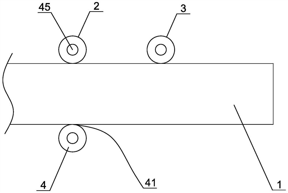
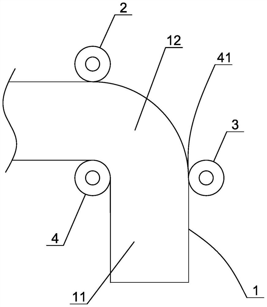
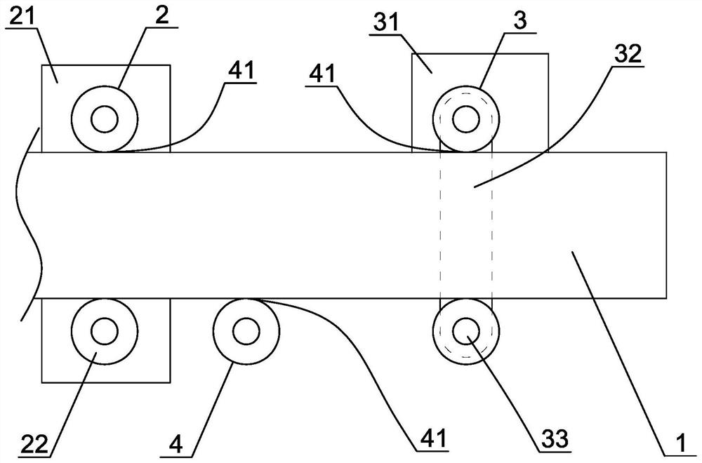
[0029] Such as figure 1 , figure 2 As shown in the figure, a portable lead wire end bender is suitable for arc bending treatment of exposed lead wire ends after stripping off the insulation layer of cables and the like. It specifically includes a first outer pressure wheel 2, a second outer pressure wheel 3, and an inner pressure wheel 4. In addition, it also includes a lead wire clamping device (not shown) that can fix and clamp the lead wire head. Of course, the first outer pressure wheel The axes of the pressure roller, the second outer pressure roller and the inner pressure roller should be parallel to each other. The first outer pressure wheel and the second outer pressure wheel are respectively associated with a linear drive mechanism, so that the first outer pressure wheel can move in the first direction, and the second outer pressure w...


PUM


Abstract

The invention discloses a portable lead wire end bender. The portable lead wire end bender comprises a first outer pressing wheel, a second outer pressing wheel and an inner pressing wheel, the first outer pressing wheel and the second outer pressing wheel are respectively linked with a linear driving mechanism, so that the first outer pressing wheel and the second outer pressing wheel can respectively move in a first direction and a second direction; the inner pressing wheel, the first outer pressing wheel and the second outer pressing wheel have a preparation state and a bending state, in the preparation state, a containing gap allowing a lead wire end to linearly penetrate through is formed between the inner pressing wheel and the first outer pressing wheel, the center connecting line of the first outer pressing wheel and the second outer pressing wheel is perpendicular to the center connecting line of the first outer pressing wheel and the inner pressing wheel, and in the bending state, the inner pressing wheel is located on the angular bisector of the first direction and the second direction, and bending gaps allowing the lead wire end to penetrate through in a bent mode are formed between the inner pressing wheel and the first outer pressing wheel and between the inner pressing wheel and the second outer pressing wheel respectively. According to the portable lead wire end bender, the bending radius and the central angle corresponding to the bent part of the bent lead wire end can be conveniently and accurately controlled, the structure is simple, and the lead wire end can be rapidly bent and formed at one time.

Description

technical field [0001] The invention belongs to the technical field of electric equipment, and in particular relates to a portable wire end bender. Background technique [0002] When laying cables, it is often necessary to bend the lead wires of the cables. At present, the bending device used for bending the lead wires has the following defects: First, the basic principle of the bending device is similar to that of the existing pipe bending. Similarly, it is rolled and bent by rollers or rollers. This bending method achieves the desired bending radius through multiple rolls and bends, or one-time bending and forming by a fixed-radius roller. When one-time bending is formed, the bending radius is determined by the corresponding roller radius. Therefore, it is inconvenient to adjust the bending radius of the lead wire after bending. However, when bending by rolling for many times, although it is beneficial to adjust the bending radius, it is difficult to accurately control th...

Claims


Application Information

Patent Timeline
Patent Type & Authority Applications(China)
IPC IPC(8): B21F1/00
CPCB21F1/004
Inventor 周钢吴轶伟吴铭叶尧平陈永权吴绍飞杨育民练正华胡为春吴红红胡玲芳吴荣芬
Owner 国网浙江省电力有限公司丽水供电公司
Why Eureka
Try Eureka