
Heat sealing mechanism of packaging machine

A technology for packaging machines and heat-sealing tubes, which is used in packaging sealing/fastening, packaging, transportation packaging, etc., can solve problems such as affecting work efficiency, low efficiency, and poor gas replacement effect, to ensure heat-sealing effect, improve The effect of work efficiency

Pending Publication Date: 2021-05-25
WENZHOU KEDI MACHINERY
View PDF0 Cites 2 Cited by
  • Summary
  • Abstract
  • Description
  • Claims
  • Application Information

AI Technical Summary

Problems solved by technology

[0002] The heat-sealing mechanism of the existing packaging machine is to drive the first heat-sealing assembly and the second heat-sealing assembly to move towards and away from each other on the horizontal plane through the telescopic rod, but a blowing and suction pipe is provided within the range of motion of the two, and the blowing and suctioning The air tube needs to be inserted into the bag during the whole process of the gas replacement period; before the blowing and suction tube runs to the heat sealing mechanism, a certain height must be kept to avoid the heat sealing mechanism, otherwise interference will occur. This avoidable height wastes a part of the blowing and suction tube The movement stroke has the disadvantage of low efficiency. After the turntable rotates to the position of the heat-sealing mechanism, the blowing and suction pipe is inserted into the packaging bag, and the heat-sealing mechanism seals the bag. However, the stroke of a single insertion is limited, and it will be easy to insert again after sealing. Wrinkles appear in the bag mouth, and the part holding the bag will cause a series of problems such as displacement or bag drop; if the length of the bag is longer, the material is more, and the particle size of the material is smaller, the effect of gas replacement will be reduced by a single insertion stroke. Not good or the material at the bottom cannot achieve the effect of gas replacement, etc. After all, the depth of a single insertion is limited, and the stroke of the mechanism for a single insertion is too large, resulting in poor transmission efficiency, etc., which affects work efficiency

Method used


Image

  • Heat sealing mechanism of packaging machine
  • Heat sealing mechanism of packaging machine
  • Heat sealing mechanism of packaging machine

Examples


Embodiment Construction

[0038] Embodiments of the present invention will be further described below in conjunction with accompanying drawings:

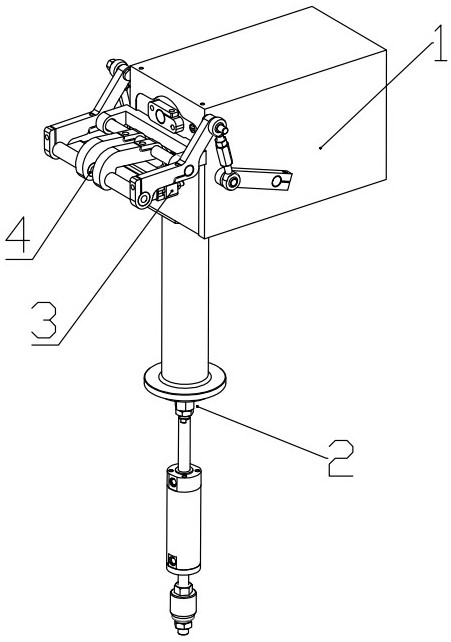
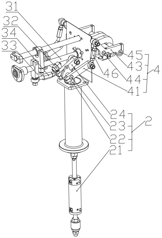
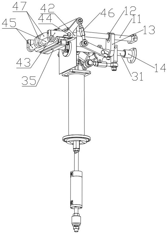
[0039] As shown in the figure, a heat-sealing mechanism of a packaging machine includes a frame 1, a drive assembly 2, and a first heat-sealing assembly 3 and a second heat-sealing assembly 4 that are oppositely arranged and move toward and away from each other synchronously. The driving assembly 2 is linked to connect the first heat-sealing assembly 3 and the second heat-sealing assembly 4 respectively, and drives the first heat-sealing assembly 3 to perform linear reciprocating motion and synchronously drives the second heat-sealing assembly 4 to perform reciprocating swinging motion. The middle section of the heat-sealing component is provided with an avoidance space; this technical solution sets the second heat-sealing component in a swinging motion state, and at the same time sets an avoidance space in its middle section, so that the blowing pipe does no...


PUM


Abstract

The invention discloses a heat sealing mechanism of a packaging machine, and relates to the field of packaging equipment. The heat sealing mechanism of the packaging machine comprises a rack, a driving assembly, a first heat sealing assembly and a second heat sealing assembly, the first heat sealing assembly and the second heat sealing assembly are oppositely arranged and do synchronous opposite separation movement, the driving assembly is in linkage connection with the first heat sealing assembly and the second heat sealing assembly, drives the first heat sealing assembly to do linear reciprocating motion, and synchronously drives the second heat sealing assembly to do reciprocating swing motion, and an avoiding space is formed in the middle section of the second heat sealing assembly. The heat sealing mechanism has the advantages of being good in heat sealing effect and high in working efficiency.

Description

technical field [0001] The invention relates to the field of packaging equipment, in particular to a heat-sealing mechanism of a packaging machine. Background technique [0002] The heat-sealing mechanism of the existing packaging machine is to drive the first heat-sealing assembly and the second heat-sealing assembly to move towards and away from each other on the horizontal plane through the telescopic rod, but a blowing and suction pipe is provided within the range of motion of the two, and the blowing and suctioning The air tube needs to be inserted into the bag during the whole process of the gas replacement period; before the blowing and suction tube runs to the heat sealing mechanism, a certain height must be kept to avoid the heat sealing mechanism, otherwise interference will occur. This avoidable height wastes a part of the blowing and suction tube The movement stroke has the disadvantage of low efficiency. After the turntable rotates to the position of the heat-se...

Claims


Application Information

Patent Timeline
Patent Type & Authority Applications(China)
IPC IPC(8): B65B51/14B65B31/06
CPCB65B51/146B65B31/06
Inventor 蔡旭光蔡建武尤传浩
Owner WENZHOU KEDI MACHINERY
Learn More