
Automobile electronic exhaust active valve structure

An automotive electronic and active technology, applied in the direction of valve housing structure, lift valve, valve details, etc., can solve problems such as increasing manufacturing difficulty, many gaps between parts and parts, and quality risks of manufacturers

Pending Publication Date: 2021-05-25
宁波经济技术开发区恒阳机械有限公司
View PDF0 Cites 1 Cited by
  • Summary
  • Abstract
  • Description
  • Claims
  • Application Information

AI Technical Summary

Problems solved by technology

[0003] However, the structure of the existing electronic exhaust valve is relatively complicated, not only the manufacturing process is complicated, the assembly is difficult, and the cost is high, but also the sealing stability of the valve body when the valve plate and the valve body are closed is poor, and the gap between parts There are many gaps, which further brings quality risks to manufacturers and increases the difficulty of manufacturing

Method used


Image

  • Automobile electronic exhaust active valve structure
  • Automobile electronic exhaust active valve structure
  • Automobile electronic exhaust active valve structure

Examples


Embodiment 1

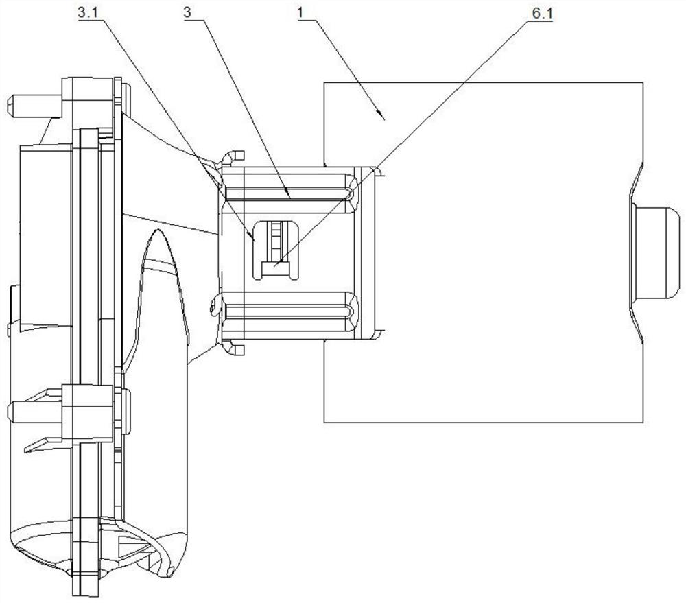
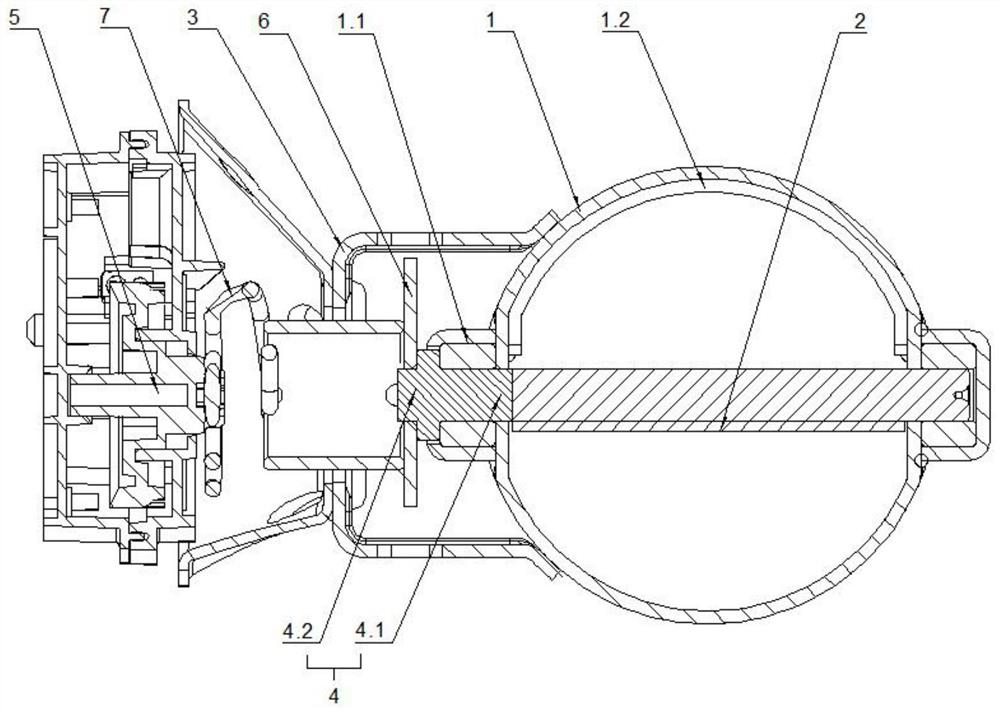
[0025] see figure 1 and figure 2 , the embodiment of the present invention provides an active electronic exhaust valve structure for automobiles, including a valve body 1, a valve plate 2, a limit seat 3, a main shaft 4 and a power source 5, and the side of the valve body 1 is provided with a socket 1.1 , the main shaft 4 is rotatably connected to the socket 1.1, the main shaft 4 includes a first end 4.1 connected with the valve plate 2 and a second end 4.2 provided with an elastic adapter, the power source 5 Used to drive the elastic adapter to rotate, the limiting seat 3 is connected to the valve body 1 , and the limiting seat 3 is provided with a positioning part for conflicting with the elastic adapter.

[0026] Compared with the prior art, the above solution can control the opening angle of the valve plate 2 by controlling the relative position of the elastic adapter and the limit seat 3, and the structure is stable and easy to adjust.

[0027] In this embodiment, the ...

Embodiment 2

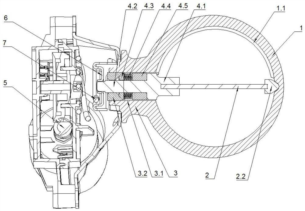
[0031] see Figure 3-Figure 5 , this embodiment 2 is basically the same as embodiment 1, the difference is that a limit ring 1.3 is provided in the jack 1.1, the main shaft 4 is inserted into the limit ring 1.3, and the middle part of the main shaft 4 is sleeved There is an aligning piece 4.3 and a spring 4.4, the aligning piece 4.3 is located between the limiting ring 1.3 and the spring 4.4, the side of the limiting ring 1.3 close to the aligning piece 4.3 is funnel-shaped, the The side of the self-aligning piece 4.3 close to the limit ring 1.3 is tapered, and the approach of the spring 4.4 is used to push the self-aligning piece 4.3 to interfere with the limit ring 1.3.

[0032] Embodiment 2 mainly achieves the effect of quickly assembling the main shaft 4 and the valve plate 2 on the valve body 1 through the setting of the limiting ring 1.3, the aligning piece 4.3 and the spring 4.4. Specifically, when assembling, the aligning piece 4.3 and the spring 4.4 are first sleeved...


PUM


Abstract

The invention discloses an automobile electronic exhaust active valve structure which comprises a valve body, a valve plate, a limiting seat, a main shaft and a power source, wherein an insertion hole is formed in the side face of the valve body, the main shaft is rotationally connected to the insertion hole, the main shaft comprises a first end connected with the valve plate and a second end provided with an elastic adapter, the power source is used for driving the elastic adapter to rotate, the limiting seat is connected to the valve body, and a positioning part used for abutting against the elastic adapter is arranged on the limiting seat. According to the scheme, the opening angle of the valve plate can be controlled by controlling the relative position of the elastic adapter and the limiting seat, the structure is stable, adjustment is convenient, the whole structure cannot be damaged due to the elastic buffering effect between the elastic adapter and the power source, and practicability is higher; and the elastic adapter can also play a role in separation of preventing gas in the valve body from being squeezed into the power source, so that the service life of the overall structure is prolonged.

Description

technical field [0001] The invention relates to the technical field of components of an automobile exhaust system, in particular to an active electronic exhaust valve structure for an automobile. Background technique [0002] Automobiles are currently the most widely used means of transportation, and family cars have become an indispensable means of transportation for people to travel. Some young people are obsessed with sports cars, but because of their limited financial capacity, they cannot own sports cars for the time being. This part of them hopes that their family cars can emit a sports car-like roar to satisfy their fantasies about sports cars. The application of electronic exhaust valves for vehicles meets the needs of these people. [0003] However, the structure of the existing electronic exhaust valve is relatively complicated, not only the manufacturing process is complicated, the assembly is difficult, and the cost is high, but also the sealing stability of the...

Claims


Application Information

Patent Timeline
Patent Type & Authority Applications(China)
IPC IPC(8): F16K1/22F16K27/02
CPCF16K1/22F16K1/224F16K27/0218
Inventor 林小山彭清龙刘建付海平卢归万志凯
Owner 宁波经济技术开发区恒阳机械有限公司
Learn More