
Air inlet net cleaning system of fan heater for smart home

A cleaning system, smart home technology, applied in separation methods, lighting and heating equipment, fluid heaters, etc., can solve the problems of underutilized waste heat, increased internal fan load, reduced life, etc., and achieve better shedding effect. , the effect of increasing the jitter frequency

Active Publication Date: 2021-05-25
广东美博智能环境设备有限公司
View PDF5 Cites 4 Cited by
  • Summary
  • Abstract
  • Description
  • Claims
  • Application Information

AI Technical Summary

Problems solved by technology

[0003] However, during the use of the existing heater, the air inlet will accumulate dust and some sundries after a period of use. If it is not disposed of in time, the load on the internal fan may increase and the service life will be shortened. In addition, after the existing heater is turned off, waste heat that has not been completely dissipated often accumulates in the heating element, and the waste heat is not fully utilized. Therefore, it is necessary to combine the waste heat with the cleaning of the filter at the air inlet. what we need to consider

Method used


Image

  • Air inlet net cleaning system of fan heater for smart home
  • Air inlet net cleaning system of fan heater for smart home
  • Air inlet net cleaning system of fan heater for smart home

Examples


Embodiment 1

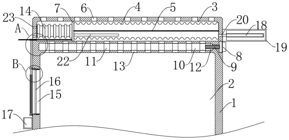
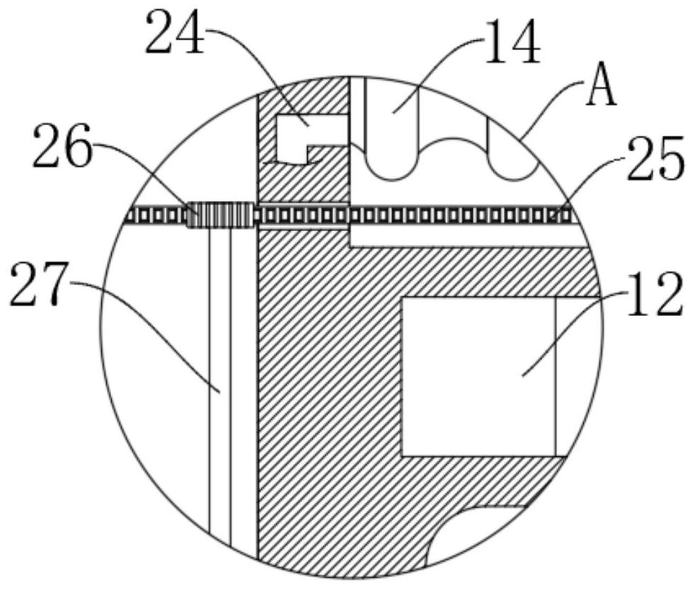
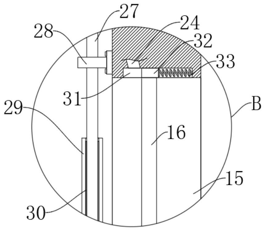
[0024] refer to Figure 1-4 , an air inlet net cleaning system for a smart home heater, comprising a heater body 1, the heater body 1 is provided with a reciprocating chamber 3, a sliding chamber 12 and a heating chamber 2 sequentially from top to bottom, and the left side of the heating chamber 2 An air inlet 15 is provided on the inner wall, and a filter screen 16 is installed in the air inlet 15. The inner top and inner bottom of the air inlet 15 are provided with chute 31, and both chute 31 are provided with sliders 32 for sliding left and right. , the right end of each slider 32 is slidably connected with the inner wall of the corresponding chute 31 through the connecting spring 33, and the opposite ends of the two sliders 32 all extend into the air inlet 15, and are fixedly connected with the upper and lower ends of the filter screen 16;

[0025] The conduction mechanism, the conduction mechanism includes a sliding bar 10 slidably connected in the sliding chamber 12, the...

Embodiment 2

[0036] refer to Figure 5-6 , The difference between this embodiment and Embodiment 1 is that the left end of the filter screen 16 is fixedly connected to the block 21 , and the cam 35 that is fixed against the block 21 is sleeved on the rotating rod 27 .

[0037] In this embodiment, under the elastic action of the connecting spring 33, the block 21 and the cam 35 are always in contact with each other, and the rotation of the rotating rod 27 will make the filter screen 16 vibrate back and forth all the time, greatly increasing the vibration frequency of the filter screen 16, thereby making The shedding effect of dust on the filter screen 16 is better.


PUM


Abstract

The invention discloses an air inlet net cleaning system of a fan heater for smart home. The air inlet net cleaning system comprises a fan heater body, the fan heater body is sequentially provided with a reciprocating cavity, a sliding cavity and a heating chamber from top to bottom, an air inlet is formed in the inner wall of the left side of the heating chamber, and a filter net is installed in the air inlet; and sliding grooves are formed in the inner top and the inner bottom of the air inlet, sliding blocks used for sliding left and right are arranged in the two sliding grooves, the right end of each sliding block is slidably connected with the inner wall of the corresponding sliding groove through a connecting spring, and the opposite ends of the two sliding blocks extend into the air inlet and are fixedly connected with the upper end and the lower end of the filter net. In the using process of the fan heater, waste heat of a heating assembly can be fully utilized, the filter net at the air inlet can be cleaned in time every time, and therefore the situation that the working load of an internal motor is increased is avoided.

Description

technical field [0001] The invention relates to the field of smart home, in particular to an air inlet net cleaning system of a heater for smart home. Background technique [0002] The heater is a warm air supply device that can be used as a family heater. Its working principle is that the air enters the unit from the suction port under the power of the fan, is heated when it flows through the air heater, and is discharged from the air outlet. It flows out of the unit to form warm air, which is sent to the heating space and forms indoor air circulation, so as to realize the heating of the indoor environment; [0003] However, during the use of the existing heater, the air inlet will accumulate dust and some sundries after a period of use. If it is not processed in time, the load on the internal fan may increase and the service life will be shortened. In addition, after the existing heater is turned off, waste heat that has not been completely dissipated often accumulates in...

Claims


Application Information

Patent Timeline
Patent Type & Authority Applications(China)
IPC IPC(8): F24H9/00B01D46/00B01D46/10B03C3/017
CPCF24H9/0052B01D46/10B03C3/0175B01D46/76Y02B30/00
Inventor 卫继芸
Owner 广东美博智能环境设备有限公司
Learn More