Circuit board flat cable detection device and detection method

A detection device and circuit board technology, which is applied in the direction of measurement device, electronic circuit test, measurement device shell, etc., can solve the problems of long circuit board repair cycle, cumbersome inspection engineering, and cumbersome inspection process, so as to reduce the defect rate of products and avoid The effect of wiring confusion and reducing production costs

Pending Publication Date: 2021-05-25
新昌县元华线束有限公司
View PDF0 Cites 0 Cited by
  • Summary
  • Abstract
  • Description
  • Claims
  • Application Information

AI Technical Summary

Problems solved by technology

In this detection method, the detection engineering is relatively cumbersome, and each function of the circuit board needs to be tried, so the detection efficiency is low, and the soldered circuit board needs to be used for detection. When a problem is detected, the repair cycle is long and the cost is high.
[0004] To sum up, the current conventional method of detecting circuit board wiring has the advantages of cumbersome detection process, low detection efficiency, long repair cycle and high repair cost for circuit boards with quality problems.

Method used


Image

  • Circuit board flat cable detection device and detection method
  • Circuit board flat cable detection device and detection method
  • Circuit board flat cable detection device and detection method

Examples


Embodiment Construction

[0032] Specific embodiments of the present invention will be described in detail below in conjunction with the accompanying drawings.

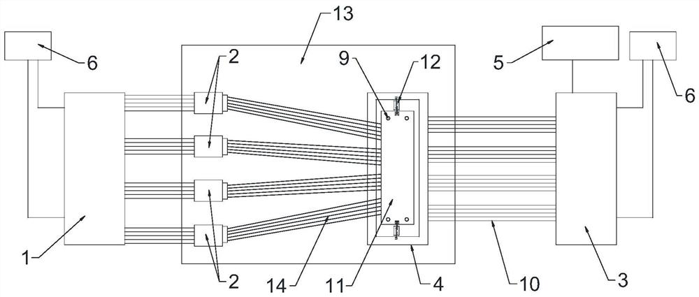
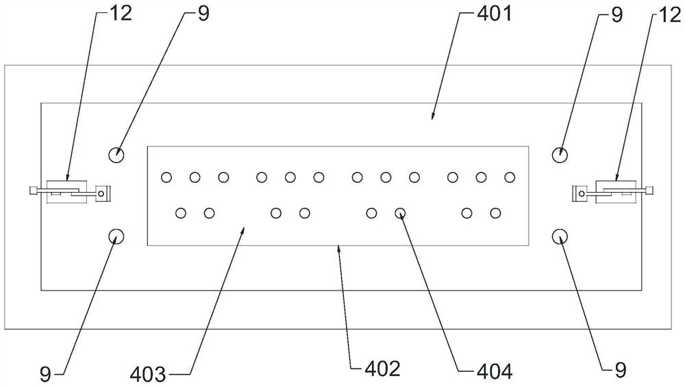
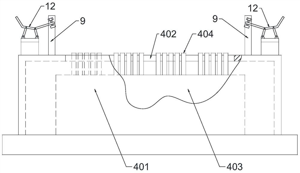
[0033] Such as Figure 1~Figure 5 As shown, the circuit board cable detection device in this embodiment includes a signal output module 1, an output terminal 2 electrically connected to the signal output module 1, a signal receiving and comparing module 3, and a detection device electrically connected to the signal receiving and comparing module 3. Seat 4, the detection result output module 5 electrically connected with the signal receiving comparison module 3 and the power supply 6 supporting the operation of the device, the detection seat 4 includes a rectangular shell 401, the upper end of the shell 401 is provided with a detection port 402, and the inside of the shell 401 is provided with An insulating base 403, a plurality of probes 404 corresponding to the cable connection points 8 on the circuit board 7 are inserted vertically on the ba...


PUM


Abstract

The invention relates to a circuit board flat cable detection device and method, and the device comprises a signal output module, an output terminal, a signal receiving module, a detection seat, a detection result output module and a power supply, the detection seat comprises a housing, the upper end of the housing is provided with a detection port, the housing is internally provided with an insulation pedestal, and a plurality of probes are vertically inserted in the pedestal. The upper end of each probe extends out of the detection port, positioning pins are respectively arranged on the upper surface of the shell at two ends of the detection port, the lower end of each probe is electrically connected with the signal receiving and comparing module, the detection seat is detachably connected with a detection clamp, and the detection clamp comprises a base and a gland. A plurality of grooves matched with the outer contour of the circuit board are formed in the base, a through hole is formed in each groove, flat cable connecting points are all right opposite to the through holes when the circuit board is embedded into the grooves, protruding blocks are arranged on the pressing cover, and when the pressing cover and the base are oppositely combined, the top portions of the protruding blocks are partially inserted into the corresponding grooves. Positioning holes corresponding to the positioning pins are formed in the base and the gland.

Description

technical field [0001] The invention relates to a circuit board wiring detection device and a detection method. Background technique [0002] The cable on the circuit board is generally formed by a plurality of wires arranged and welded on the circuit board. Each wire transmits a different signal. The end of the cable away from the circuit board will be made into a terminal. The position of each wire on the terminal is Fixed, so the order of the wiring (that is, the order in which each wire is connected to the circuit board) is wrong will cause signal transmission errors, resulting in the function of the circuit board cannot be realized normally, so the circuit board needs to be corrected after connecting the wiring. Check the wiring to ensure that the board can be used normally. [0003] The conventional method of detecting circuit board wiring is to pre-install the soldered circuit board on an analog device, and then check whether the functions of the circuit board can op...

Claims


Application Information

Patent Timeline
IPC IPC(8): G01R31/28G01R1/04G01R1/067
CPCG01R1/0408G01R1/06711G01R31/2808
Inventor 龙卫锋张斌
Owner 新昌县元华线束有限公司
Why Eureka
Try Eureka