Connection mode of optical module and heat dissipation mechanism

A technology of heat dissipation mechanism and connection method, which is applied in the field of connection between optical modules and heat dissipation mechanisms, can solve problems such as increasing plugging resistance, affecting heat dissipation effect, and damaging the surface of optical modules, so as to reduce processing quality requirements and improve heat dissipation performance. , the effect of reducing operating resistance

Pending Publication Date: 2021-05-25
武汉英飞光创科技有限公司
View PDF0 Cites 4 Cited by
  • Summary
  • Abstract
  • Description
  • Claims
  • Application Information

AI Technical Summary

Problems solved by technology

[0003] This method is widely used, but there are always the following problems: 1. During the process of plugging and unplugging the optical module, it is always under the pressure of the heat sink, resulting in friction, which not only damages the surface of the optical module, but also increases the plugging resistance; 2. The heat sink and the optical The pressure on the surface of the module cannot fully guarantee the heat transfer effect, so that high-power optical modules need to increase the flatness and roughness of the top surface to improve heat dissipation, although some optical module protocols (such as QSFP-DD and OSFP) allow heat sinks on the module , but it is only limited to the part where the cage is not inserted, and increases the processing difficulty of the optical module casing, and its size is limited by the agreement, which affects the heat dissipation effect

Method used


Image

  • Connection mode of optical module and heat dissipation mechanism
  • Connection mode of optical module and heat dissipation mechanism
  • Connection mode of optical module and heat dissipation mechanism

Examples


Embodiment 1

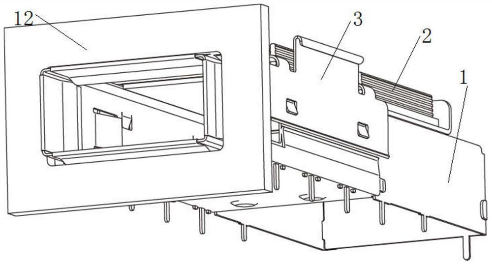
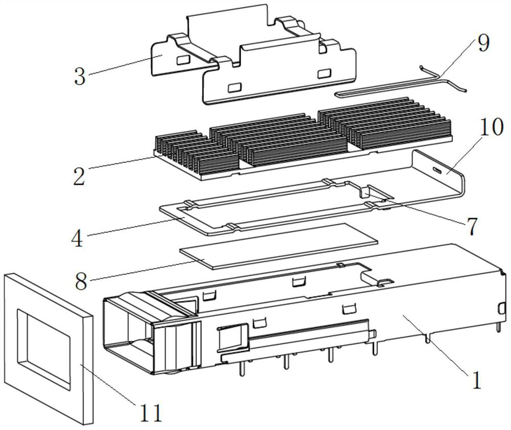
[0033] see Figure 1-2 , the embodiment of the present invention provides a connection method between an optical module and a heat dissipation mechanism. The heat dissipation mechanism includes a cage body. A cage radiator is hung outside the cage body through a spring clip. An adjustment mechanism is provided between the cage body and the cage radiator. The adjustment mechanism There is a reset mechanism on it. When the optical module is inserted into the cage body, it touches the adjustment mechanism and drives the adjustment mechanism to move horizontally, thereby causing the cage radiator to descend under the action of the spring clip. The bottom surface of the cage radiator contacts the optical module, and the optical module is pulled out from the cage body. , the adjustment mechanism can be reset under the action of the reset mechanism, so that the heat sink of the cage rises and separates from the optical module.

[0034] The entrance of the cage body is connected to t...

Embodiment 2

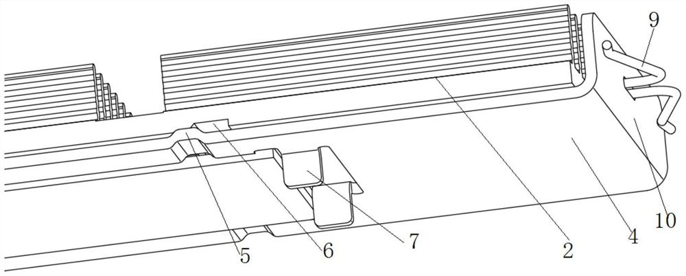
[0040] see Figure 5-6 , the embodiment of the present invention provides a connection method between an optical module and a heat dissipation mechanism. The heat dissipation mechanism includes a cage body. A cage radiator is hung outside the cage body through a spring clip. An adjustment mechanism is provided between the cage body and the cage radiator. The adjustment mechanism There is a reset mechanism on it. When the optical module is inserted into the cage body, it touches the adjustment mechanism and drives the adjustment mechanism to move horizontally, thereby causing the cage radiator to descend under the action of the spring clip. The bottom surface of the cage radiator contacts the optical module, and the optical module is pulled out from the cage body. , the adjustment mechanism can be reset under the action of the reset mechanism, so that the heat sink of the cage rises and separates from the optical module.

[0041]The entrance of the cage body is connected to th...

Embodiment 3

[0046] see Figure 7 , 8 , and the difference from Embodiment 1 is that in this embodiment, the reset device adopts a handle, and the handle is used for manual reset. The handle is arranged near the entrance of the cage, and a through hole is opened on the equipment panel for the handle to pass through.


PUM


Abstract

The invention provides a connection mode of an optical module and a heat dissipation mechanism. The heat dissipation mechanism comprises a cage body; a cage radiator is externally hung above the cage body through a spring clip; an adjusting mechanism is arranged between the cage body and the cage radiator; a reset mechanism is arranged on the adjusting mechanism; when the optical module is inserted into the cage body, the optical module contacts with the adjusting mechanism and drives the adjusting mechanism to move horizontally, so that the cage radiator descends under the action of the spring clip, the bottom surface of the cage radiator contacts with the optical module; and when the optical module is pulled out of the cage body, the adjusting mechanism can reset under the action of the reset mechanism, so that the cage radiator ascends and is separated from the optical module. According to the connection mode of the invention, an existing connection mode of the optical module and the heat dissipation mechanism is improved, the processing quality requirement on the surface of the optical module is reduced, the pressure on an optical module circuit board is reduced, the heat dissipation performance is greatly improved, the optical module is not rubbed with the cage radiator when being plugged and unplugged, the operation resistance is greatly reduced, a hand feeling is obvious, and the surface of the optical module is not easy to damage.

Description

technical field [0001] The invention relates to the technical field of optical module heat dissipation, in particular to a connection method between an optical module and a heat dissipation mechanism. Background technique [0002] In the field of optical communication, there are a large number of hot-swappable optical module development agreements (MSA), including SFP / SFP28 / DSFP / QSFP / QSFP+ / QSFP28 / QSFP-DD / OSFP / XFP / CFP / CFP2 / CFP4 / CFP8 / CXP / CDFP / SNAP12, etc. In the future, MSA upgrades will still use the hot-swappable module method. In order to facilitate the replacement of hot-swappable optical modules, the single board of the customer equipment will be equipped with a cage to guide and fix the optical module. This determines that the part where the optical module is inserted into the cage cannot be designed with a heat sink, but needs to be plugged into the cage. The heat sink is used to dissipate heat for the optical module. The current heat sink is buckled above the cage w...

Claims


Application Information

Patent Timeline
Patent Type & Authority Applications(China)
IPC IPC(8): G02B6/42
CPCG02B6/4269
Inventor 刘寅龙
Owner 武汉英飞光创科技有限公司
Why Eureka
Try Eureka