
Energy-consuming steel rod replaceable beam-column joint node and construction method thereof

A beam-column connection and steel bar technology, which is applied to building components, earthquake resistance, building types, etc., can solve the problems of complex construction, poor structural floor integrity, and difficulty in replacing the embedded parts of the connection, so as to achieve a simple connection method and good waterproof performance. , the effect of easy operation

Pending Publication Date: 2019-09-20
CHINA STATE CONSTRUCTION ENGINEERING CORPORATION
View PDF0 Cites 6 Cited by
  • Summary
  • Abstract
  • Description
  • Claims
  • Application Information

AI Technical Summary

Problems solved by technology

[0003] The purpose of the present invention is to provide a beam-column connection node with replaceable energy-dissipating steel rods and its construction method. It is necessary to solve the complex construction and inconvenient installation of energy-dissipating steel bars in the traditional beam-column joints when setting energy-dissipating steel bars. The construction of energy-dissipating steel bars in the reserved holes is complicated, the integrity of the structural floor is poor, the waterproof performance between floors is difficult to guarantee, the connecting embedded parts are difficult to replace after the earthquake, and the structural repair after the earthquake is difficult.

Method used


Image

  • Energy-consuming steel rod replaceable beam-column joint node and construction method thereof
  • Energy-consuming steel rod replaceable beam-column joint node and construction method thereof
  • Energy-consuming steel rod replaceable beam-column joint node and construction method thereof

Examples


Embodiment Construction

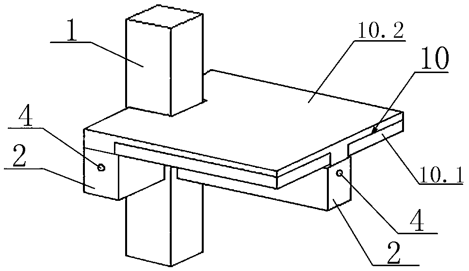
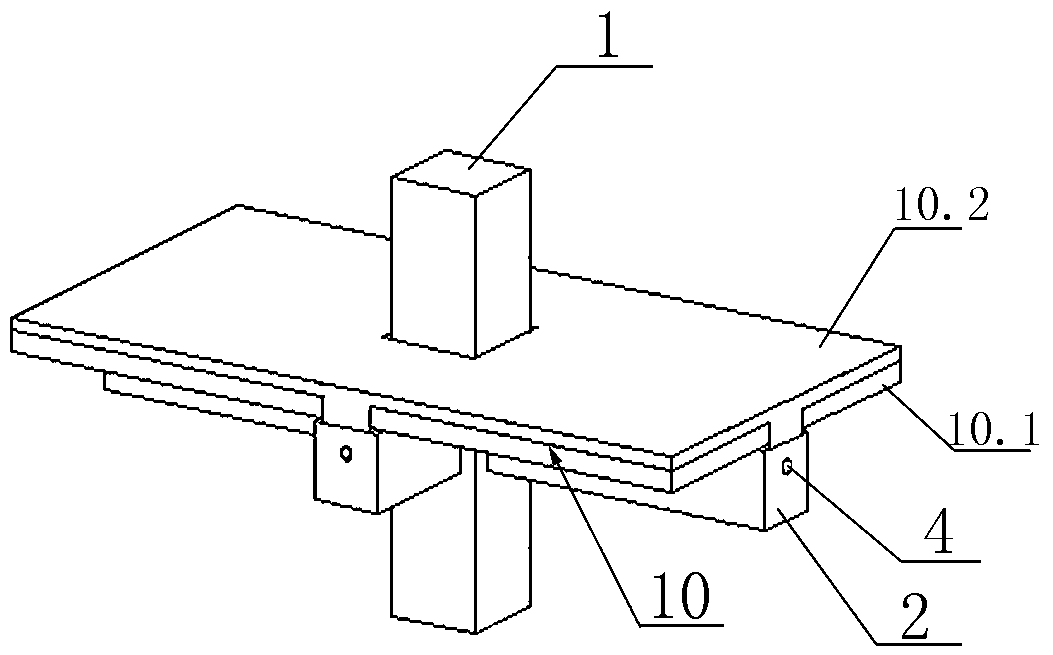
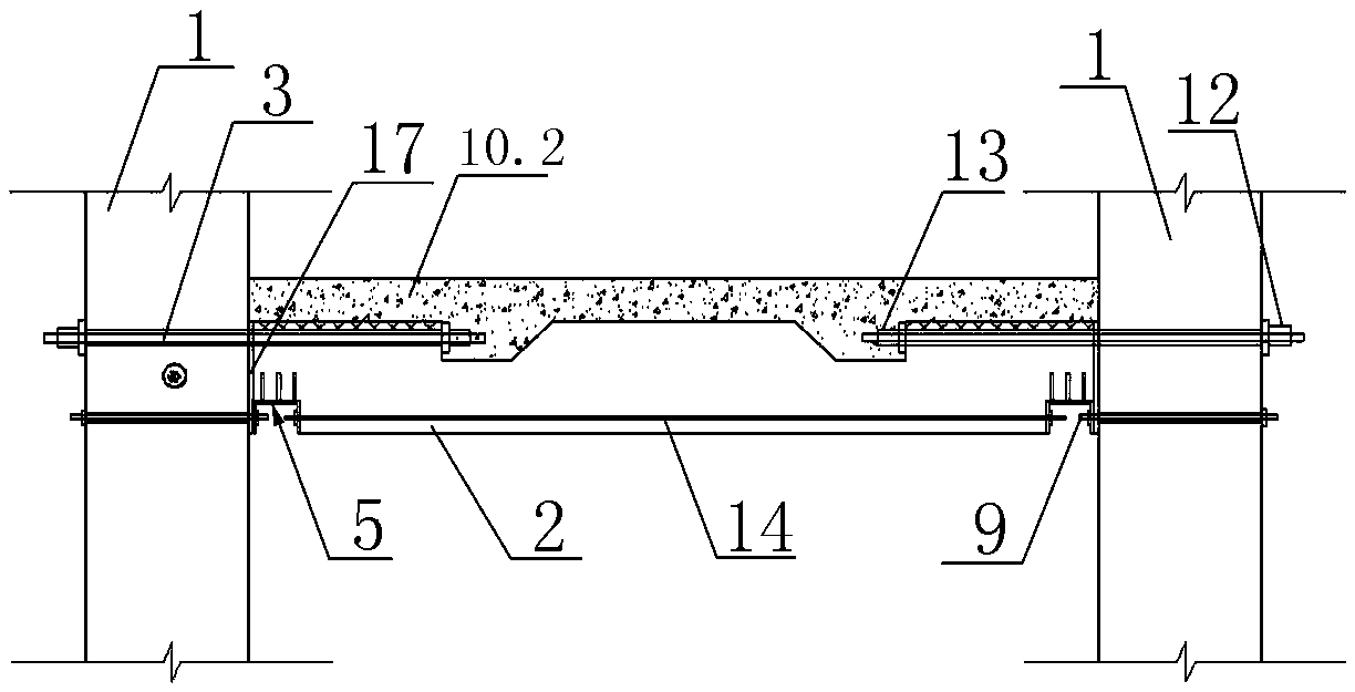
[0042] Such as Figure 1-10As shown, the beam-to-column connection node with replaceable energy-dissipating steel rods includes frame columns 1, prefabricated beams 2, prestressed tendons 3 and laminated floor slabs 10; the laminated floor slabs 10 include prefabricated slabs 10.1 and existing Pouring the composite layer 10.2; the prefabricated beam 2 is provided with a prestressed tendon tunnel 4; the frame column 1 is provided with a reinforcement tunnel 6 at a position corresponding to the prestressed tendon tunnel 4; the prestressed tendons 3 are pierced Provided in the prestressed tendon channel 4 and the reinforced channel 6, the prefabricated beam 2 and the frame column 1 are crimped and connected; a bonding material 17 is provided in the joint between the prefabricated beam 2 and the frame column 1; the prefabricated The bottom of the beam 2, near the two ends, is provided with a connection assembly 5; the connection assembly 5 includes a rectangular box 5.1 surrounded...


PUM


Abstract

The invention relates to an energy-consuming steel rod replaceable beam-column joint node and a construction method thereof, which comprises a frame column, a precast beam, a prestressing tendon, and a laminated floor.A prestressing tendon channel is formed in the prestressing beam; a through tendon channel is formedin the position corresponding to the prestressing tendon channel in the frame column; the prestressing tendon is arranged in the prestressing tendon channel and a through tendon channel; the bottom of the precast beam near the both ends is provided witha connecting component; the connecting component comprises a rectangular box which is enclosed by four vertical side plates and a top plate and a vertical connecting rod connected to the top of the rectangular box; a lower side of the vertical side plate near one side of the frame column is provided with a notch; a connecting channel is formed inthe position corresponding to the notch in the frame column; and an energy-consuming steel rod is worn in the connecting channel. The construction method solves the difficult technical problems, comprising complicated construction of the traditional beam-column joints, the inconvenient installation of the energy-consuming steel bars, the complicated installation of the energy-consuming steel bars in the upper part of the prefabricated beams, the poor integrity of the structural floor panels, the difficulty in waterproofing between the floors, the difficulty in replacing the connected components after the earthquake, and the structural repair after the earthquake.

Description

technical field [0001] The invention belongs to the field of construction engineering, in particular to a beam-column connection node with replaceable energy-consuming steel rods and a construction method thereof. Background technique [0002] At present, the domestic prefabricated concrete frame structure system mainly adopts beam-column disconnection at the node connection, prefabricated in sections, and the beam-column node area is cast in-situ at the construction site to form an assembled integral structural system. The dry connection system of beam-column joints is limited to setting corbels supporting prefabricated beams on prefabricated columns. The two are usually connected by steel plate embedded parts or inserted ribs, and the ability to transfer beam end bending moments is poor. Such joints with poor seismic performance are mainly used in plant structures. There are prefabricated prestressed frame dry joints without corbels used in civil buildings in the United S...

Claims


Application Information

Patent Timeline
IPC IPC(8): E04B1/21E04B1/98E04H9/02
CPCE04B1/215E04H9/021
Inventor 齐虎付青青刘康郭海山耿娇谭康
Owner CHINA STATE CONSTRUCTION ENGINEERING CORPORATION
Learn More