Bookshelf capable of freely adjusting placing space
A bookshelf and space technology, applied in the field of bookshelves, can solve problems such as inability to adjust, books falling, and single fixation, and achieve the effect of avoiding falling and moving
- Summary
- Abstract
- Description
- Claims
- Application Information
AI Technical Summary
Problems solved by technology
Method used
Image
Examples
Embodiment 1
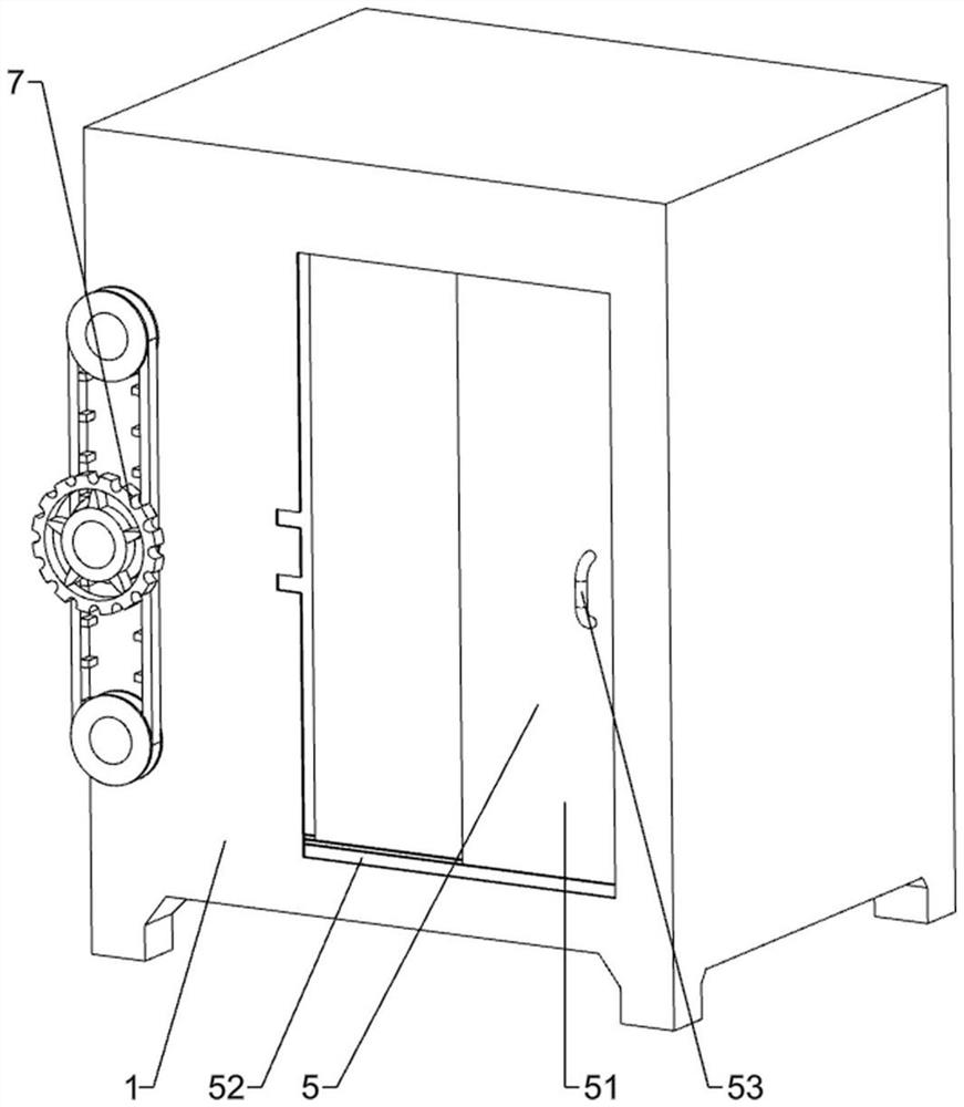
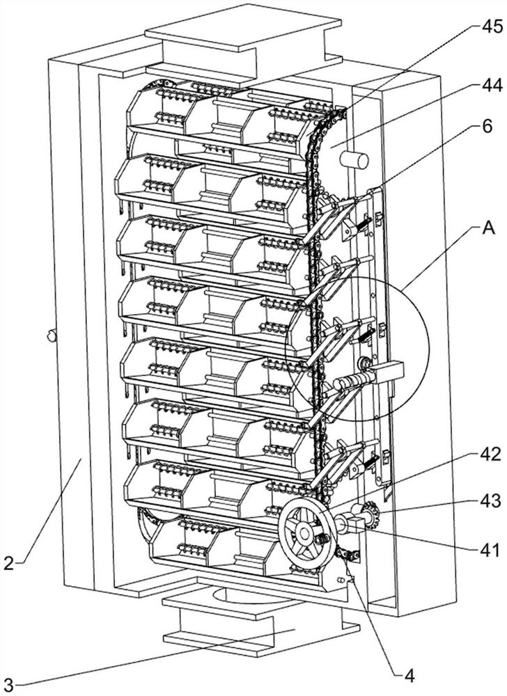
[0025] A free adjustable space bookshelf, such as Figure 1-Figure 3 Shown, comprise supporting cabinet 1, movable bookshelf 2, movable slider 3, rotating mechanism 4 and dust-proof mechanism 5, all sliding type is provided with movable slider 3 up and down both sides in the supporting cabinet 1, movable slider 3 up and down both sides A movable bookshelf 2 is arranged in a rotating manner among the 3, a rotating mechanism 4 is arranged between the support cabinet 1 and the movable bookshelf 2, and a dustproof mechanism 5 is provided on the support cabinet 1.
[0026] Rotating mechanism 4 comprises transmission shaft 41, movable runner 42, reversing bevel gear 43, transmission sprocket assembly 44, movable bearing frame 45 and limit post 46, and the lower side of support cabinet 1 right part is provided with transmission shaft 41 in a rotational manner, Drive shaft 41 front portion circumferential direction is fixedly connected with movable runner 42, and movable bookshelf 2 i...
Embodiment 2
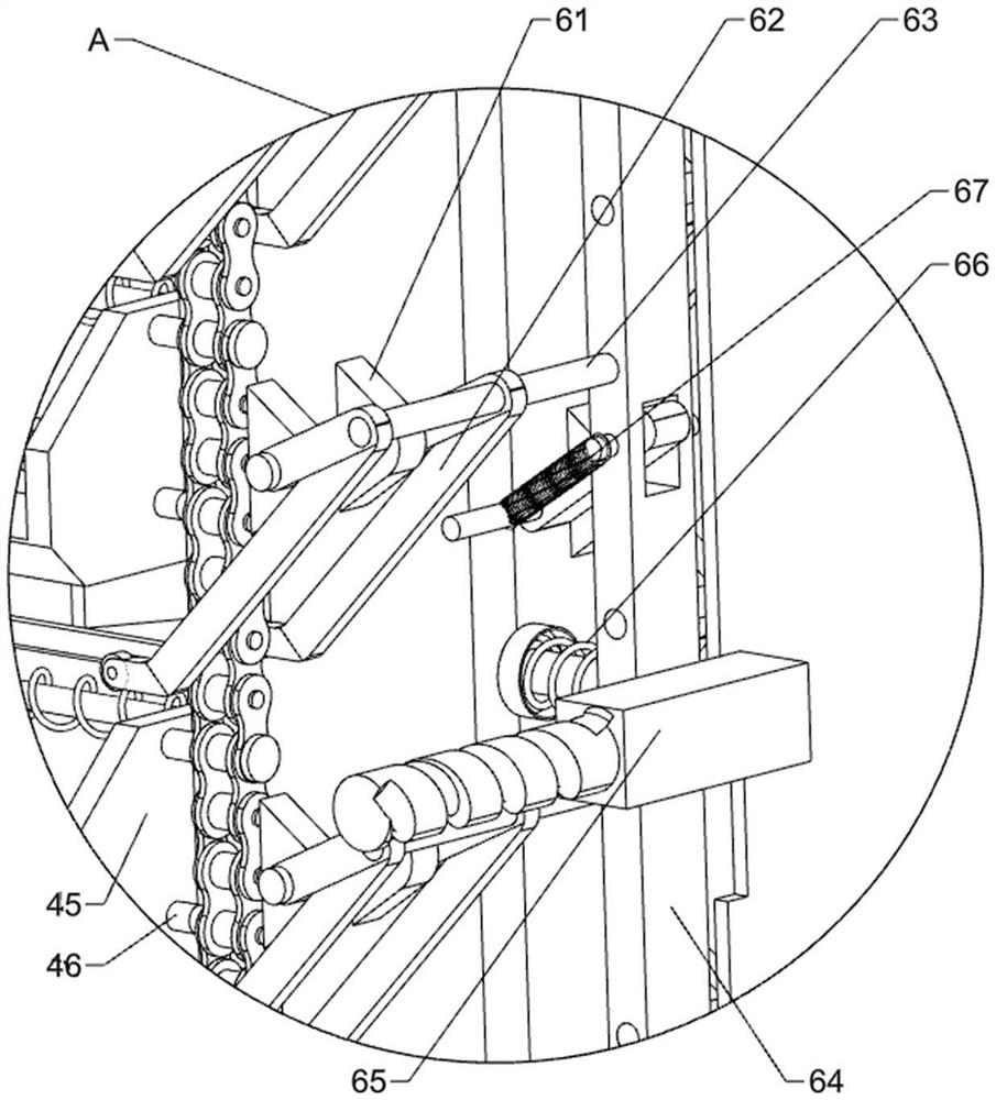
[0030] On the basis of Example 1, such as Figure 2-Figure 4 As shown, it also includes a locking mechanism 6, and the locking mechanism 6 includes a fixed angle seat 61, a locking connecting rod 62, a push rod 63, a linkage straight plate 64, a force block 65, a limiting spring 66 and a locking spring 67 , the left and right sides of the movable bookshelf 2 are evenly spaced with fixed corner seats 61, hinged between the two fixed corner seats 61 is provided with a locking link 62, and the outer side of the locking link 62 is rotatably provided with a push rod 63, The left and right sides of the movable bookshelf 2 are hingedly provided with a linkage straight plate 64, the inner end of the push rod 63 is fixedly connected with the linkage straight plate 64, and the middle part of the linkage straight plate 64 is slidingly provided with a force block 65, and the force block 65 slides with the support cabinet 1 Cooperate, the limit spring 66 is wound between the inner side of ...
Embodiment 3
[0035] On the basis of embodiment 1 and embodiment 2, such as Figure 4 and Figure 5 As shown, it also includes a storage load-bearing mechanism 8, and the storage load-bearing mechanism 8 includes a storage stool 81, a positioning link 82 and a hydraulic rod 83, and four storage stools 81 are provided at the right front part of the bottom of the support cabinet 1, and four storage stools 81 are provided. Evenly spaced rotation between stools 81 is provided with positioning connecting rod 82, and between the left and right sides positioning connecting rod 82 is provided with hydraulic pressure rod 83.
[0036] Also include clamping mechanism 9, clamping mechanism 9 includes clamping plate 91, guide rod 92 and compression spring 93, is provided with two guide rods 92 between the left and right sides in the movable carrier frame 45, two guide rods Between 92, left and right symmetrical sliding type is provided with clamping plate 91, between the clamping plate 91 outer surface...
PUM
 Abstract
Description
Claims
Application Information
 - R&D
- Intellectual Property
- Life Sciences
- Materials
- Tech Scout
- Unparalleled Data Quality
- Higher Quality Content
- 60% Fewer Hallucinations
Browse by: Latest US Patents, China's latest patents, Technical Efficacy Thesaurus, Application Domain, Technology Topic, Popular Technical Reports.
© 2025 PatSnap. All rights reserved.Legal|Privacy policy|Modern Slavery Act Transparency Statement|Sitemap|About US| Contact US: help@patsnap.com


