Minimally invasive adenoid ablation device
A technology of adenoid and shell, applied in the field of minimally invasive adenoid removal device, which can solve the problems of fine-tuning the ablation site and achieve accurate resection and prevent damage
- Summary
- Abstract
- Description
- Claims
- Application Information
AI Technical Summary
Problems solved by technology
Method used
Image

Examples
Embodiment 1
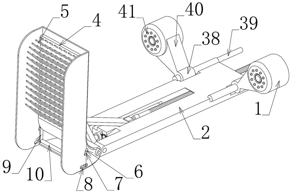
[0040] Embodiment 1, its technical solution is to include a camera 1, which is characterized in that it also includes an extension plate 2 extending into the nasopharyngeal cavity, and the front end of the extension plate 2 is fixedly connected with a protective shell 3, which is located in the protective shell The lower end of the body 3 is rotatably connected to an adenoid elimination plate 4, and a plurality of plasma needles 5 are fixedly connected to the adenoid elimination plate 4. Corresponding moving shafts 6 are also fixedly connected to the front and rear sides of the lower end of the elimination plate 4, and arc-shaped moving grooves 7 are respectively provided on the protective housing 3 corresponding to the positions of the moving shafts 6. The center of rotation of the lower end of the adenoid elimination plate 4 is arranged, and the front and rear ends of the protective shell 3 are located at the lower ends of each arc-shaped moving groove 7. Displacement grooves 8...
Embodiment 2
[0042] Embodiment 2. On the basis of Embodiment 1, the drive connection device includes a drive shaft 15 that is rotated and laterally slidably connected to the extension plate 2, and the left end surface of the drive shaft 15 is provided with an internal shaft that matches the drive gear 14. Gear 16, the middle part of the drive shaft 15 is an external gear shaft 17 and meshes with the second gear 18 that is rotatably connected on the extension plate 2, and the second gear 18 is connected with the third gear 19 that is rotatably connected on the extension plate 2 The third gear 19 is meshed with the driving driving wheel 20 which is rotatably connected to the extension plate 2, and the right end surface of the driving driving wheel 20 is coaxially fixedly connected with the first manual rotating rod protruding to the right. 21, the right end of the drive shaft 15 is coaxially connected with a rotating ring 22, the rotating ring 22 is fixedly connected with a vertically arrange...
Embodiment 3
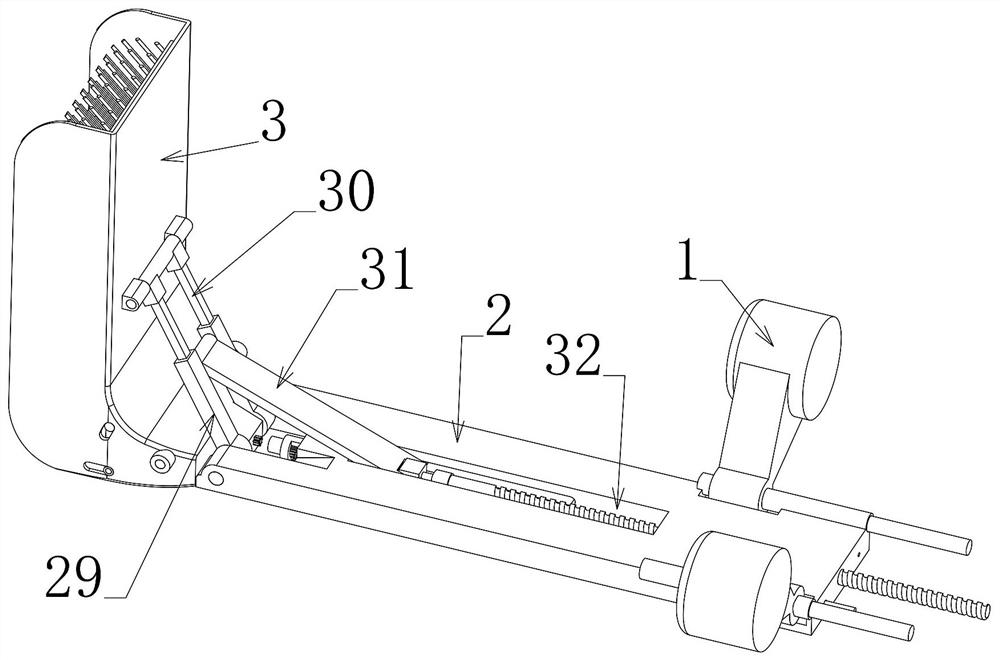
[0044] Embodiment 3, on the basis of Embodiment 1, the posture adjustment device includes an adjustment frame 29 that is coaxially rotatably connected to the rotating connection part between the protective shell 3 and the extension plate 2. The adjustment frame 29 protrudes upwards and has a Vertically arranged square chute, the vertical line in the square chute is slidingly connected with a matching frame 30, the upper end of the matching frame 30 is connected to the right end surface of the protective shell 3 in rotation, and the upper end of the adjustment frame 29 is fixedly connected with a longitudinally arranged adjustment support rod 9. The adjustment support rod 9 is rotatably connected with an adjustment connection rod 31, and the upper end surface of the extension plate 2 is provided with an adjustment groove 32 arranged horizontally and having the same width as the adjustment support rod 9, and the front and rear sides of the adjustment groove 32 are respectively pro...
PUM
 Abstract
Description
Claims
Application Information
 - R&D
- Intellectual Property
- Life Sciences
- Materials
- Tech Scout
- Unparalleled Data Quality
- Higher Quality Content
- 60% Fewer Hallucinations
Browse by: Latest US Patents, China's latest patents, Technical Efficacy Thesaurus, Application Domain, Technology Topic, Popular Technical Reports.
© 2025 PatSnap. All rights reserved.Legal|Privacy policy|Modern Slavery Act Transparency Statement|Sitemap|About US| Contact US: help@patsnap.com