Hydraulic oil filtering device utilizing negative pressure

A hydraulic oil filtration and negative pressure technology, which is applied in the field of hydraulic oil filtration, can solve problems such as the inability to judge the state of the filter element, broken hydraulic oil pipes, and complex structures.

Inactive Publication Date: 2021-05-28
TIANJIN UNIV MARINE TECH RES INST +1
View PDF3 Cites 0 Cited by
  • Summary
  • Abstract
  • Description
  • Claims
  • Application Information

AI Technical Summary

Problems solved by technology

[0004] First of all, hydraulic pumps are used to provide power, and the requirements for hydraulic pumps are relatively high. Hydraulic pumps are required to work in both directions. When filtering, hydraulic pumps must be relied on. When using hydraulic oil after filtration, hydraulic pumps are also required to pump it out. Secondly, it is used to The filtered filter element needs to be removed and cleaned after being used for a period of time. If a hydraulic pump is used to provide power, due to the high pressure generated by the hydraulic pump, the hydraulic oil can still pass through smoothly even if the filter element has been clogged. It is difficult to guarantee the filtering effect, that is, when the hydraulic pump is used to filter the hydraulic oil, the state of the filter element cannot be judged, and it can only be confirmed by disassembly and assembly. However, due to the large number of filters used for filtration and the complicated structure, it is difficult to disassemble and assemble. At the same time, the gasket must be replaced every time it is disassembled. If the clean filter is disassembled and cleaned, it will waste time and money
Finally, when filtering the hydraulic oil, the hydraulic oil that is enough for the glider to use multiple times is generally filtered at one time, so the filtering time is longer, and it is easy to pay attention to the volume of the oil in the oil tank during manual operation. If the pump is not turned off in time, it will be damaged. Cause the hydraulic oil to overflow the oil tank, and it is more likely that the hydraulic oil pipe will be broken

Method used


Image

  • Hydraulic oil filtering device utilizing negative pressure
  • Hydraulic oil filtering device utilizing negative pressure

Examples


Embodiment Construction

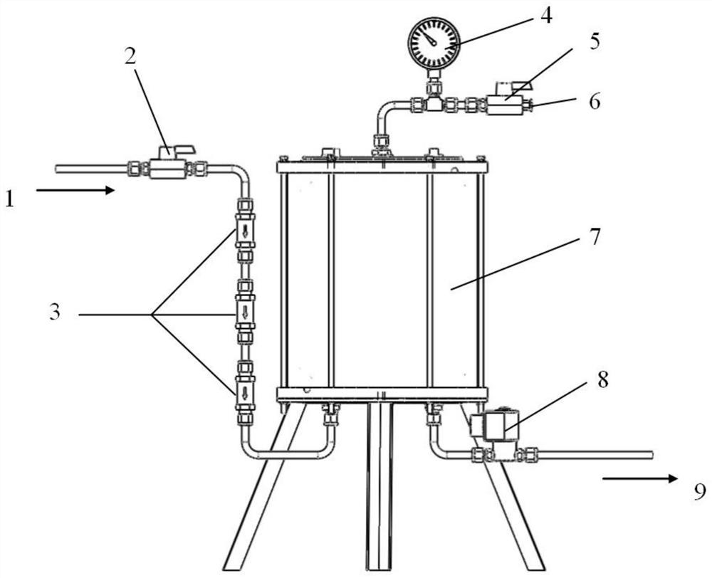
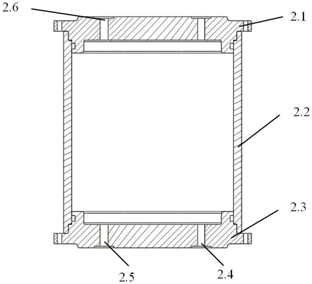
[0011] A hydraulic oil filter device using negative pressure, such as figure 1 and figure 2 As shown, a negative pressure oil tank 7 is provided, and the negative pressure oil tank 7 is provided with an upper end cover 2.1, a lower end cover 2.3 and a tank body 2.2; Connect with the pneumatic joint 6 in sequence; the lower end cover 2.3 of the negative pressure oil tank 7 is provided with an oil suction port 2.4 and an oil discharge port 2.5, and the oil suction port 2.4 is connected with the filter 3 and the hand valve 2 in sequence, and there are 3 filters 3; the oil discharge port 2.5 is connected to the solenoid valve 8; the two end caps of the negative pressure oil tank 7 and the tank body 2.2 are sealed with an O-ring; the hydraulic oil enters the filter system from the oil inlet 1, and enters the filter system after being filtered by the three-stage filter 3 Store in the negative pressure oil tank 7.

[0012] When starting to filter, first connect the oil inlet 1 to ...


PUM


Abstract

The invention provides a hydraulic oil filtering device utilizing negative pressure. The device is provided with a negative pressure oil tank, and the negative pressure oil tank is provided with an upper end cover, a lower end cover and a tank body. The upper end cover is provided with an extraction opening, and the extraction opening is sequentially connected with a negative pressure meter, a control hand valve and a pneumatic connector; the lower end cover of the negative pressure oil tank is provided with an oil suction port and an oil discharge port, and the oil suction port is sequentially connected with three filters and a hand valve; the oil discharge port is connected with the electromagnetic valve; o-shaped rings are used for sealing between two end covers of the negative pressure oil tank and the tank body; according to the device, hydraulic oil is filtered through the pressure difference generated by negative pressure, due to the fact that the pressure difference generated by the negative pressure is limited, under the same negative pressure condition, when the oil return speed becomes slow, it is prompted that the filter needs to be cleaned, and it is prevented that the clean filter is detached due to misjudgment. Due to the fact that the negative pressure changes along with the change of the volume of the hydraulic oil in the oil tank, if the negative pressure is not increased manually when the oil tank is about to be filled with oil, the pressure difference enabling the hydraulic oil to pass through the filter cannot be provided, and the situation that the oil tank is filled with excessive oil can be avoided.

Description

technical field [0001] The invention belongs to the field of hydraulic oil filtering, in particular to a hydraulic oil filtering device utilizing negative pressure. Background technique [0002] Underwater glider is a new type of ocean exploration equipment, which uses buoyancy drive to operate continuously in the ocean for several months, with a range of thousands of kilometers. Its buoyancy drive system generally uses hydraulic oil as the working medium, and relies on the hydraulic oil to be discharged out of the pressure shell or sucked back into the pressure shell to change its own buoyancy. [0003] Since the components of the buoyancy system have requirements for the cleanliness of the hydraulic oil, there must be no particles or impurities exceeding a certain size in the hydraulic oil, otherwise it will cause damage to the components, or even cause damage to the components or cause them to fail to work. Filtration is required before official use to remove various imp...

Claims


Application Information

Patent Timeline
IPC IPC(8): B01D35/02B01D35/143F15B21/04
CPCB01D35/02B01D35/143F15B21/041B01D2201/204
Inventor 王树新王延辉杨绍琼张连洪张宏伟刘玉红
Owner TIANJIN UNIV MARINE TECH RES INST
Why Eureka
Try Eureka