Multi-stage injection type water-soluble waste gas recovery system and waste gas recovery process

A waste gas recovery and spraying technology, which is applied in the direction of dispersed particle filtration, transportation and packaging, and dispersed particle separation, can solve the problems of poor solution, waste, solution waste, etc., and achieve accurate measurement results, full response, and avoid solution waste. Effect

Inactive Publication Date: 2021-05-28
六安健筠环保技术有限公司
View PDF1 Cites 0 Cited by
  • Summary
  • Abstract
  • Description
  • Claims
  • Application Information

AI Technical Summary

Problems solved by technology

[0002] In the process of general industrial production, a large amount of waste gas will be generated. According to the emission standard, the general waste gas will be filtered by the filter device and then discharged. At present, the recycling of resources is advocated worldwide. Therefore, some equipment that recycles waste gas also produces Yes, when these devices recycle waste gas, they use a certain proportion of the solution to react with the recyclable substances in the waste gas for recycling, but these solutions are only mixed within a certain range when they are configured, which leads to the use of It is impossible to choose a solution with a better effect for the reaction, which will result in the need for multiple reactions to reach the required standard, wasting a lot of time and waste more solutions with poor effect to reach the standard, and the current spray method is used The reaction method, in this way, the contact between the solution and the exhaust gas is not sufficient, and more solution is needed for the reaction, which will also cause too much waste of the solution

Method used


Image

  • Multi-stage injection type water-soluble waste gas recovery system and waste gas recovery process
  • Multi-stage injection type water-soluble waste gas recovery system and waste gas recovery process
  • Multi-stage injection type water-soluble waste gas recovery system and waste gas recovery process

Examples


Embodiment 1

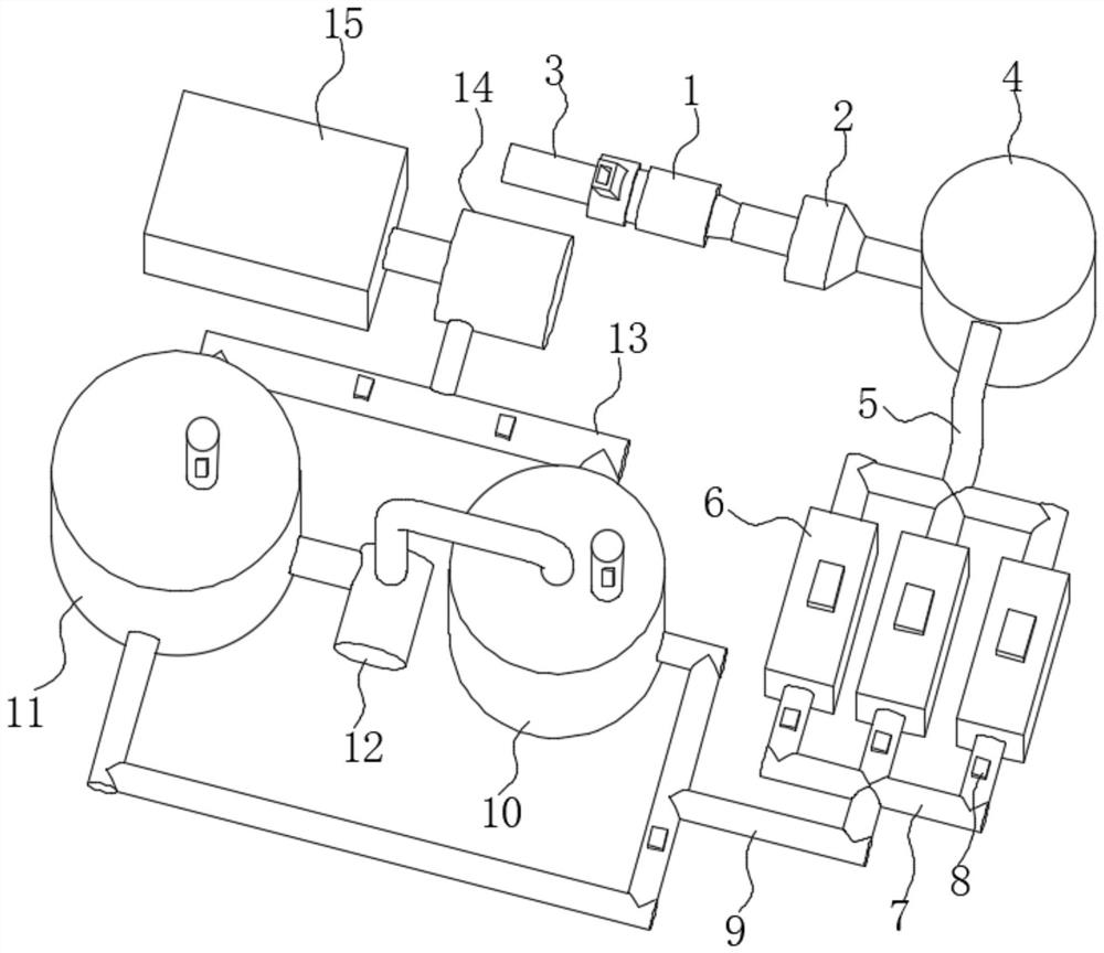
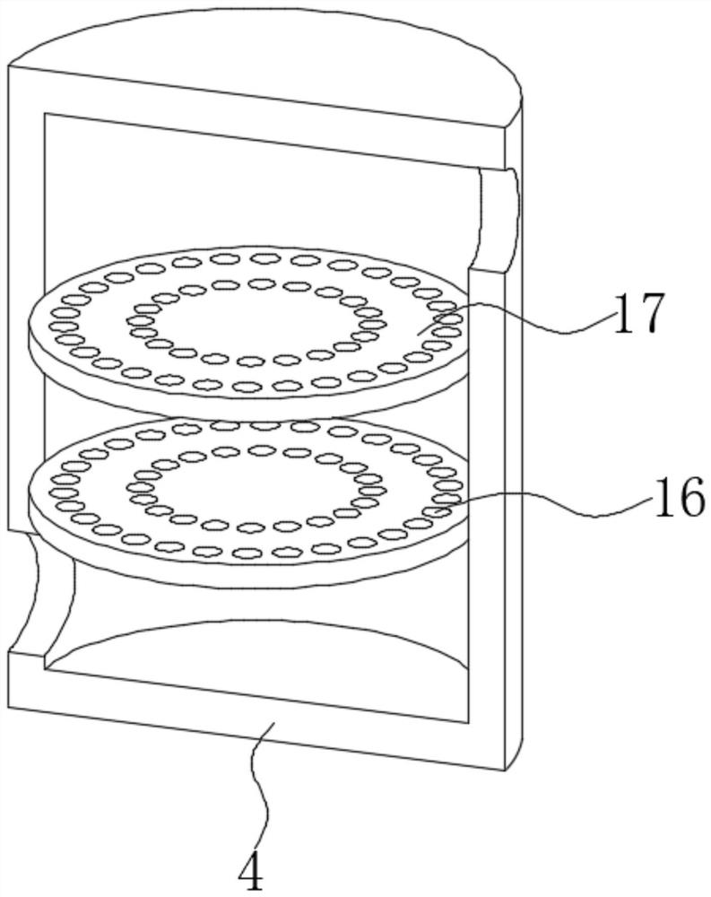
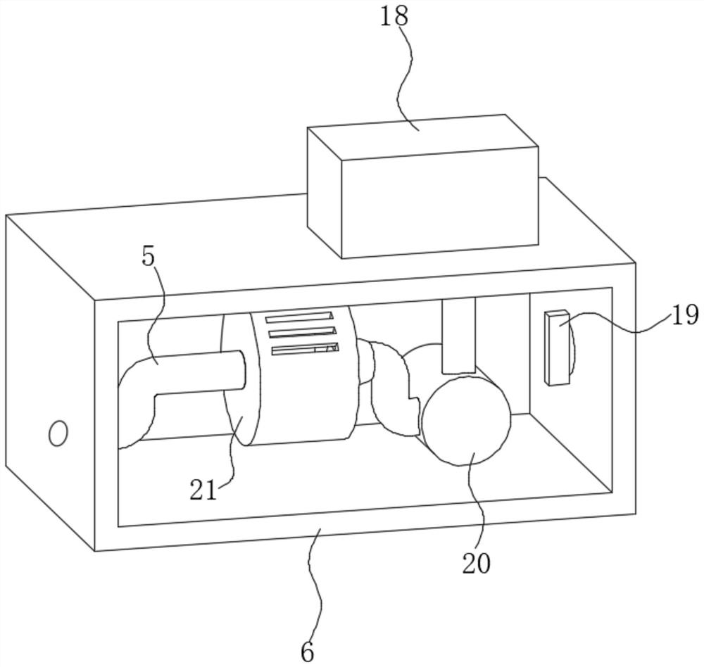
[0038] see Figure 1-6 , a multi-stage jet-type water-soluble exhaust gas recovery system and exhaust gas recovery process, including an injector 1, the right end of the injector 1 is fixedly connected with a flame arrester 2, and the left side of the injector 1 is fixedly connected with an intake pipe 3, and the flame arrester 2 The right end of the first three-terminal connecting pipe 5 is fixedly connected with the primary filter chamber 4 through the connecting pipe, and the outer wall of the primary filtering chamber 4 is fixedly connected with the first three-terminal connecting pipe 5 near the top. The front ends of the three branch pipes of the first three-terminal connecting pipe 5 are all The measuring chamber 6 is fixedly connected, and the front sides of the three measuring chambers 6 are fixedly connected with the second three-terminal connecting pipe 7, and the outer walls of the three branch pipes of the second three-terminal connecting pipe 7 are all fixedly con...


PUM


Abstract

The invention discloses a multi-stage injection type water-soluble waste gas recovery system and a waste gas recovery process, and belongs to the field of waste gas recovery. The multi-stage injection type water-soluble waste gas recovery system comprises an injector, the left end of the injector is fixedly connected with a flame arrester, the right side of the injector is fixedly connected with a gas inlet pipe, and the left end of the flame arrester is fixedly connected with a primary filter chamber through a communicating pipe; a first three-end communicating pipe is fixedly connected to the position, close to the top end, of the outer wall of the primary filtering chamber, measuring chambers are fixedly connected to the front ends of three branch pipes of the first three-end communicating pipe, and second three-end communicating pipes are fixedly connected to the front sides of the three measuring chambers; and the second three-end communicating pipes are connected with a first absorption tower and a second absorption tower through first two-end communicating pipes, the first absorption tower and the second absorption tower are connected with a water pump, and the water pump is connected with a liquid storage chamber. Through the primary filter chamber, the three measuring chambers and the absorption towers, waste gas is filtered and then fully mixed with an atomized solution, the contact degree of the solution and the waste gas is improved, the solution is saved, and waste is avoided.

Description

technical field [0001] The invention relates to the field of waste gas recovery, more specifically, to a multi-stage jetting water-soluble waste gas recovery system and a waste gas recovery process. Background technique [0002] In the process of general industrial production, a large amount of waste gas will be generated. According to the emission standard, the general waste gas will be filtered by the filter device and then discharged. At present, the recycling of resources is advocated worldwide. Therefore, some equipment that recycles waste gas also produces Yes, when these devices recycle waste gas, they use a certain proportion of the solution to react with the recyclable substances in the waste gas for recycling, but these solutions are only mixed within a certain range when they are configured, which leads to the use of It is impossible to choose a solution with a better effect for the reaction, which will result in the need for multiple reactions to reach the requir...

Claims


Application Information

Patent Timeline
Patent Type & Authority Applications(China)
IPC IPC(8): B01D53/78B01D53/75B01D53/38B01D46/12
CPCB01D53/78B01D53/75B01D53/38B01D46/12B01D46/62
Inventor 计雪莲
Owner 六安健筠环保技术有限公司
Why Eureka
Try Eureka