Automatic stretching and glue injection equipment for armored tube of armored optical cable

A technology for armored optical cable and armored tube, which is applied in the field of automatic stretching and glue injection equipment for armored optical cable and armored tube, can solve the problems of low gluing efficiency, great physical injury, poor gluing effect, etc., so as to improve efficiency Effect

Inactive Publication Date: 2021-05-28
李小毛
View PDF9 Cites 0 Cited by
  • Summary
  • Abstract
  • Description
  • Claims
  • Application Information

AI Technical Summary

Problems solved by technology

[0004] In the prior art, when the armored tube of the armored optical cable is processed, it is manually stretched, and then glue is applied to the stretched gap to fill the gap. After the glue is applied, the glue is evenly spread, and then the fan is used to The glue is dried and cured, and finally manually wound. The efficiency of manual stretching and gluing is low and the effect of gluing is not good, which affects the subsequent use of the armored optical cable armor tube, and each manpower needs to be completed for 8 hours a day. More than 1,000 stretching and gluing actions, long-term bending actions will cause great harm to the body, and the work intensity is also extremely high, so it is urgent to use automated equipment to replace

Method used


Image

  • Automatic stretching and glue injection equipment for armored tube of armored optical cable
  • Automatic stretching and glue injection equipment for armored tube of armored optical cable
  • Automatic stretching and glue injection equipment for armored tube of armored optical cable

Examples


Embodiment Construction

[0034] The technical solutions of the present invention will be clearly and completely described below in conjunction with the accompanying drawings. Apparently, the described embodiments are some of the embodiments of the present invention, but not all of them.

[0035] The components of the embodiments of the invention generally described and shown in the figures herein may be arranged and designed in a variety of different configurations. Accordingly, the following detailed description of the embodiments of the invention provided in the accompanying drawings is not intended to limit the scope of the claimed invention, but merely represents selected embodiments of the invention.

[0036] Based on the embodiments of the present invention, all other embodiments obtained by persons of ordinary skill in the art without making creative efforts belong to the protection scope of the present invention.

[0037] In the description of the present invention, it should be noted that the...


PUM


Abstract

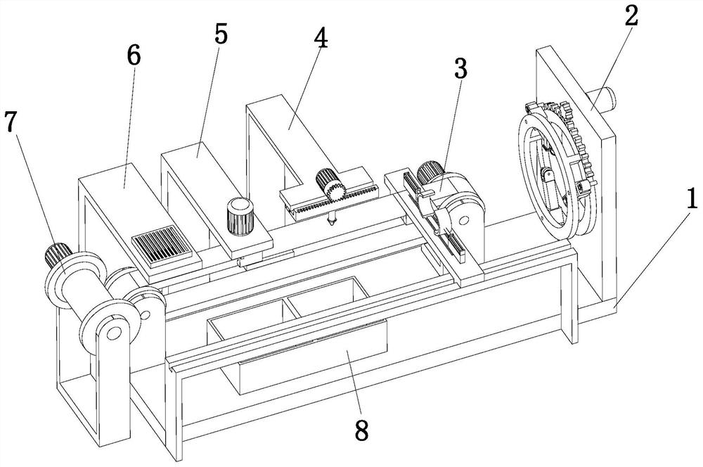
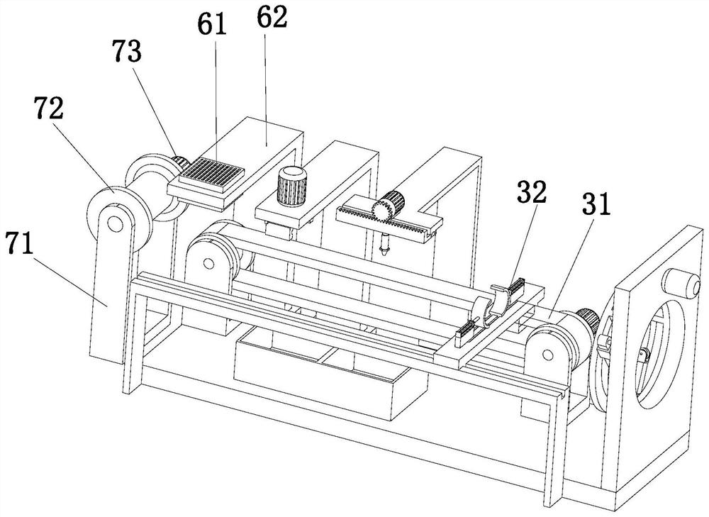
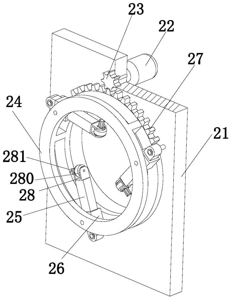
The invention discloses automatic stretching and glue injection equipment for an armored tube of an armored optical cable, and belongs to the technical field of optical cable processing. The automatic stretching and glue injection equipment comprises a supporting plate, a movable limiting device, a stretching and fixing device, a glue coating device, a glue smearing device, a drying device and a winding device; the supporting plate is arranged horizontally, the moving limiting device is arranged at the top of the supporting plate and located at the end of one side of the supporting plate, the stretching and fixing device is arranged at the top of the supporting plate and comprises a stretching assembly and a fixing assembly, the stretching assembly is horizontally arranged on the supporting plate, and the fixing assembly is arranged on the stretching assembly and is in sliding fit with the stretching assembly; and the gluing device, the glue smearing device and the drying device are sequentially arranged on the side of the supporting plate, and the winding device is arranged on the side of the supporting plate and located at the end of the other side of the supporting plate. The automatic stretching and glue injection operation of the armor tube of the armored cable can be realized, and the working efficiency is improved.

Description

technical field [0001] The invention relates to the technical field of optical cable processing, in particular to an automatic drawing glue injection equipment for armored optical cable armor tube. Background technique [0002] Armored optical cables have important applications in telecommunications optical fiber long-distance lines and primary and secondary trunk line transmission. However, the armored optical cables commonly encountered by general network management are mostly used to connect two optical fiber network devices used in the internal building of the computer room. Such armored cables are relatively short in length and are often called armored jumpers. The armored tube of the armored optical cable can prevent the damage to the optical fiber of the optical cable caused by the stretching of the laying construction wiring of the optical cable. The metal armored tube is surrounded by aramid material (Kevlar) to make the optical cable have a tensile strength of abo...

Claims


Application Information

Patent Timeline
Patent Type & Authority Applications(China)
IPC IPC(8): B05B13/04B05B15/00B05B13/02B05B12/12G02B6/44
CPCB05B12/124B05B13/0221B05B13/0436B05B15/00G02B6/4439
Inventor 李小毛
Owner 李小毛
Why Eureka
Try Eureka