Multi-connected turbine cutting device and cutting method

A cutting device and multi-unit technology, which is applied in the direction of grinding drive device, grinding/polishing safety device, manufacturing tools, etc., can solve the problems of low cutting efficiency, poor cutting precision, troublesome operation, etc., and achieve high cutting efficiency, Good clamping adaptability and good automation

Active Publication Date: 2021-05-28
WUXI RUICHANG PRECISION CASTING CO LTD
View PDF4 Cites 0 Cited by
  • Summary
  • Abstract
  • Description
  • Claims
  • Application Information

AI Technical Summary

Problems solved by technology

The cutting method of multi-connected turbines in the prior art is as follows: first, the multi-connected turbines are positioned by a special positioning tool, and pressed and fixed with a pressure plate, and then the multi-connected turbines are cut off one by one with a hand-held grinder. Loosen the multi-piece turbine on the special tool for the first time, turn over and turn it, and then press it again with the pressure plate, and then cut it. The disadvantages are: more troublesome operation, poor cutting accuracy, low cutting efficiency, and poor safety.

Method used


Image

  • Multi-connected turbine cutting device and cutting method
  • Multi-connected turbine cutting device and cutting method
  • Multi-connected turbine cutting device and cutting method

Examples


Embodiment 1

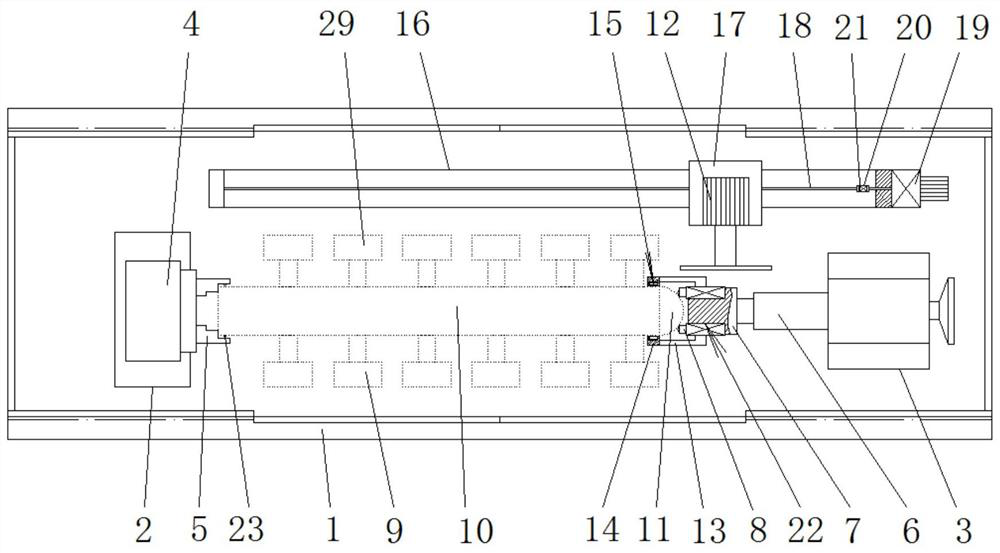
[0034] Such as Figures 1 to 4Shown is an embodiment of a multi-conjoined turbine cutting device of the present invention, including a workpiece positioning and fixing tool and a grinding wheel moving cutting tool, and the workpiece positioning and fixing tool includes a base plate 1 and a left base arranged on the base plate 1 2 and the right base 3, the left base 2 is equipped with an index plate 4 facing the direction of the right base 3, the index plate 4 is equipped with a three-jaw self-centering chuck 5, the right A telescopic sleeve 6 pointing to the direction of the left base 2 is installed on the base 3, and a rotating thimble 7 is installed on the front end of the telescopic sleeve 6, and the rotating thimble 7 is a modified type rotating thimble, and the modified type rotates The front end of the thimble is flattened and three floating support cylinders 8 are installed at the outer circumference of the front end of the rotating thimble 7, and the front end of the f...

Embodiment 2

[0047] A kind of cutting method that adopts the multiple conjoined turbine cutting device of embodiment 1, comprises the steps:

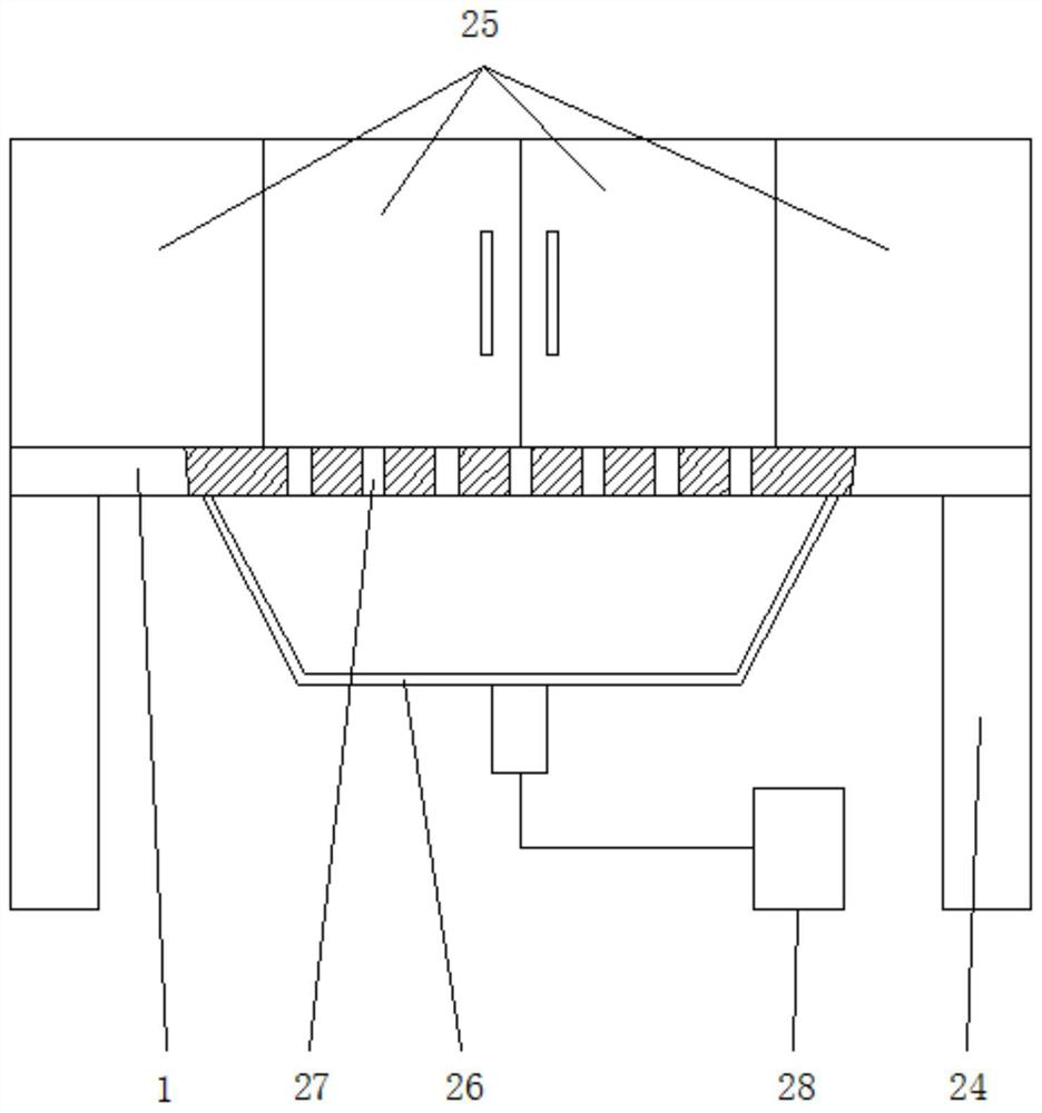
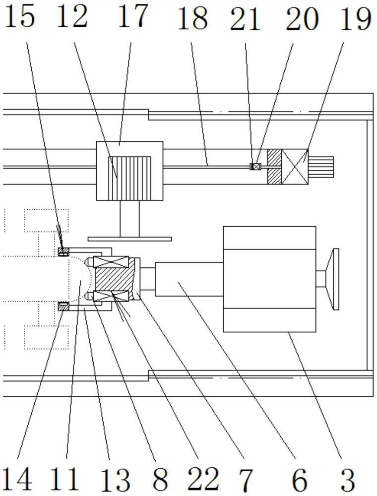
[0048] (1) workpiece installation: open the combined movable transparent shield 25, and carry out the clamping of the workpiece; The claw self-centering chuck 5 clamps the outer circle of the flat end of the intermediate shaft of the multi-joint turbine 9, and finally passes through the three floating support cylinders 8 to the ball end of the intermediate shaft of the multi-joint turbine 9 11 The surface of the blank realizes three-point floating resistance and locking; wherein, when clamping the outer circle of the spherical end 11 of the intermediate shaft of the multi-connected turbine 9, the spherical end 11 of the intermediate shaft of the multi-connected turbine 9 The outer circle is inserted into the inner hole of the annular hollow air ring 15, and the inner hole of the annular hollow air ring 15 is uniformly shrunk by filling the annular h...


PUM


Abstract

The invention discloses a multi-connected turbine cutting device and a cutting method. The cutting device comprises a base plate, a left base and a right base, wherein the left base and the right base are arranged on the base plate; an index plate is installed on the left base; a three-jaw self-centering chuck is installed on the index plate; a telescopic sleeve is installed on the right base; a rotating ejector pin is installed at the front end of the telescopic sleeve; the rotating ejector pin is a modified rotating ejector pin; the front end of the modified rotating ejector pin is flattened; three floating supporting cylinders are installed at the outer circle position of the front end of the rotating ejector pin; the front end ejector heads of the floating supporting cylinders point to the direction of the left base; and the rotation axis of the index plate is coaxial with the rotation axis of the rotating ejector pin. During clamping, the outer circle of the flat head end of a middle shaft of a multi-connected turbine is positioned and clamped through the three-jaw self-centering chuck, the ball head end of the middle shaft of the multi-connected turbine is supported and locked in a three-point floating mode through the three floating supporting cylinders, and a grinding machine is arranged beside the multi-connected turbine. According to the multi-connected turbine cutting device and the cutting method provided by the invention, efficient and automatic cutting of the multi-connected turbine is achieved.

Description

technical field [0001] The invention relates to the technical field of turbine manufacturing, in particular to a multi-connected turbine cutting device and a cutting method. Background technique [0002] The manufacture of small and medium-sized turbines is often cast by multi-unit lost-wax casting. After casting, multiple blank turbines are connected together on an intermediate shaft that was originally used as a casting crucible; Lines are arranged and arranged at intervals, and several rows of turbine groups are arranged on the outer circle of an intermediate shaft to form a multi-connected turbine. One end of the intermediate shaft has a ball head, and the other end is a flat mouth. The specific structure is as follows: figure 2 The conjoined turbine 10 in. [0003] After the casting of multi-connected turbines is completed, each single turbine needs to be cut off from the intermediate shaft. The cutting method of multi-connected turbines in the prior art is as follow...

Claims


Application Information

Patent Timeline
Patent Type & Authority Applications(China)
IPC IPC(8): B24B27/06B24B55/00B24B41/06B24B55/06B24B47/12B24B47/20B24B49/00B24B1/00
CPCB24B27/0675B24B27/0683B24B27/0608B24B55/00B24B41/06B24B55/06B24B47/12B24B47/20B24B49/00B24B1/00Y02P70/10
Inventor 勇铁军
Owner WUXI RUICHANG PRECISION CASTING CO LTD
Why Eureka
Try Eureka