Belt conveyor

A technology of belt conveyor and transmission device, which is applied in the direction of conveyor, conveyor objects, transportation and packaging, etc., and can solve the problem that the motor cannot be moved out

Active Publication Date: 2021-05-28
TANGSHAN XIELI RUBBER BELT TRANSPORTING EQUIPCO
View PDF6 Cites 4 Cited by
  • Summary
  • Abstract
  • Description
  • Claims
  • Application Information

AI Technical Summary

Problems solved by technology

The inspection robot of the present invention is capable of autonomous inspection and real-time communication, and performs intelligent fault diagnosis on the belt conveyor during the inspection process, but the invention cannot remove the motor when the conveyor belt is overloaded and the motor stops, and Provides some level of removal of excess material on the conveyor belt

Method used


Image

  • Belt conveyor
  • Belt conveyor
  • Belt conveyor

Examples


specific Embodiment approach 1

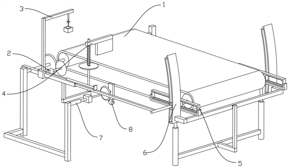
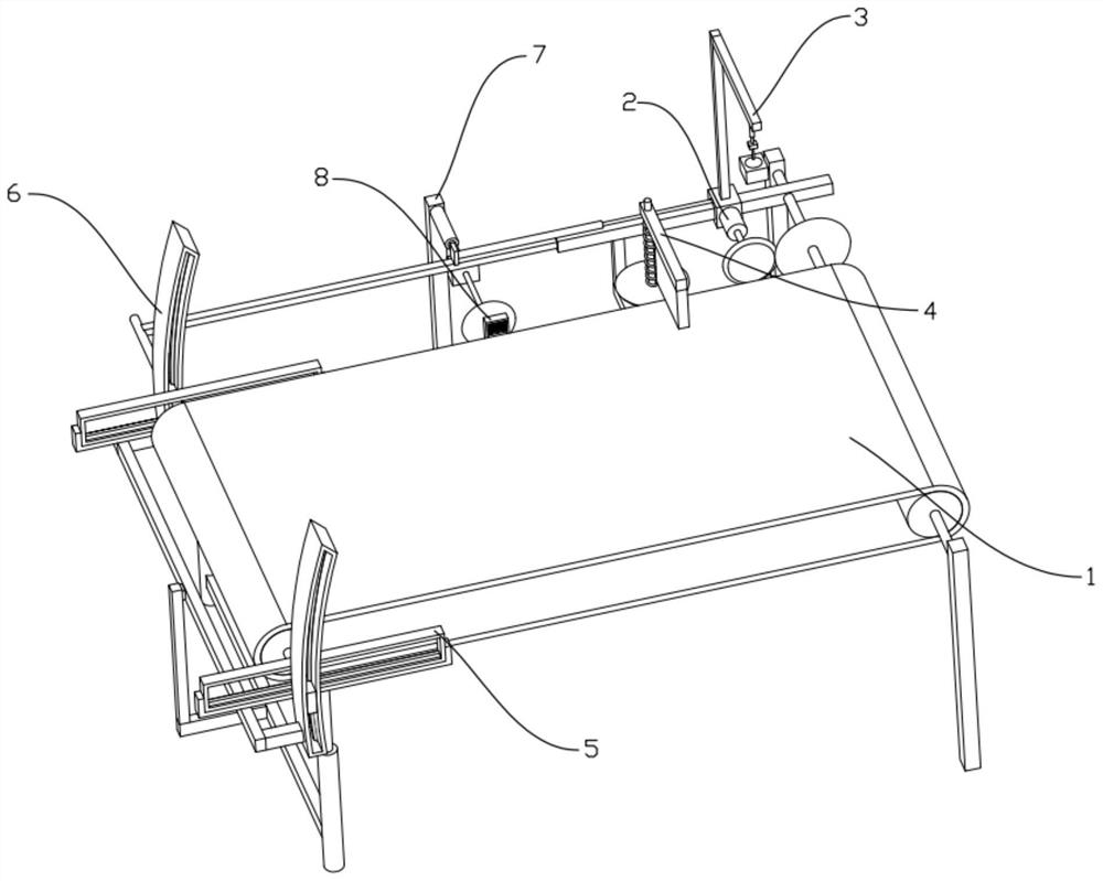
[0029] Combine below figure 1 , 2 , 3, 4, 5, 6, 7, 8, 9, and 10 illustrate this embodiment. The present invention relates to the field of industrial equipment, more specifically a belt conveyor, including a transmission device 1, a drive device 2, a trigger Slider mechanism 3, scraping mechanism 4, inclined support device 5, sliding device 6, matching device 7 and beating device 8, it is characterized in that: described driving device 2 is connected on trigger slider mechanism 3, trigger slider mechanism 3 is connected to the conveying device 1, the scraping mechanism 4 is connected to the conveying device 1, the inclined supporting device 5 is connected to the conveying device 1, the sliding device 6 is connected to the inclined supporting device 5, and the matching device 7 is connected to the conveying device 1, The beating device 8 is connected to the matching device 7, and the motor can be moved out when the conveyor belt is overloaded and the motor stops, and the excess...

specific Embodiment approach 2

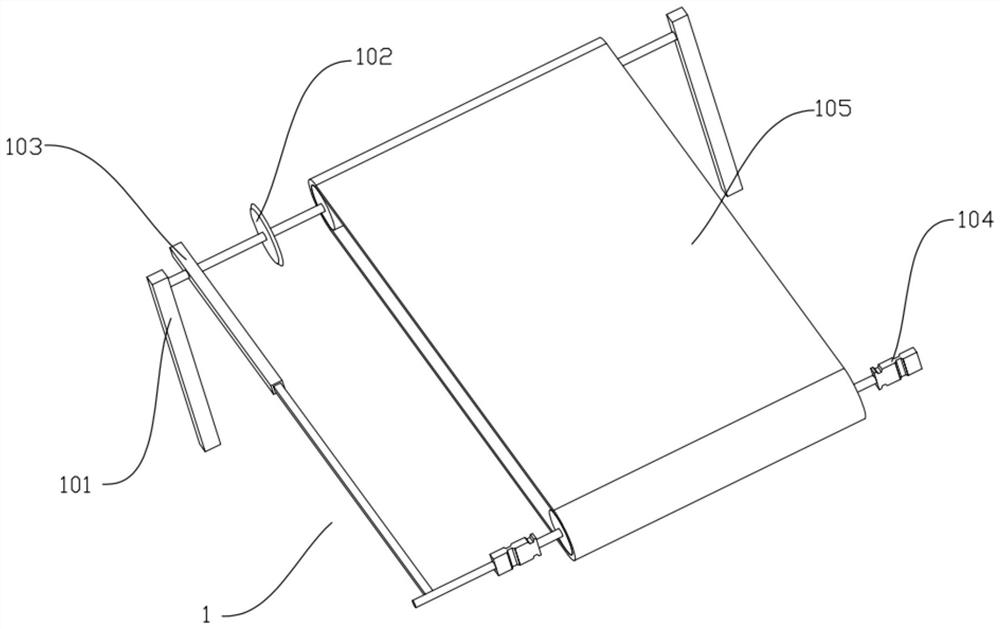
[0031] Combine below figure 1 , 2 , 3, 4, 5, 6, 7, 8, 9, and 10 illustrate this embodiment, and this embodiment will further describe Embodiment 1. The transmission device 1 includes a support column I101, a first gear 102, and a connecting rod 103 1. The multi-slide slider 104 and the conveyor belt 105, the first gear 102 is fixedly connected to the left end of the front side of the conveyor belt 105, the left and right ends of the front side of the conveyor belt 105 are respectively connected to the two supporting columns I101 in rotation, and the connecting rod 103 is fixedly connected to the conveyor belt 105 The left end of the front side, the left and right sides of the rear end of the conveyor belt 105 are respectively rotatably connected to two multi-slideway sliders 104, and the left side multi-slideway slider 104 is fixedly connected to the rear end of the connecting rod 103, and the materials to be transported are placed on the conveyor belt 105, the driving device...

specific Embodiment approach 3

[0033] Combine below figure 1 , 2 , 3, 4, 5, 6, 7, 8, 9, and 10 illustrate this embodiment, and this embodiment will further describe Embodiment 1. The drive device 2 includes a motor 201 and a second gear 202, and the second gear 202 Fixedly connected to the output shaft of the motor 201, the second gear 202 meshes with the first gear 102, the motor 201 rotates to drive the second gear 202 to rotate, the second gear 202 rotates to drive the first gear 102 to rotate, and the first gear 102 rotates the conveyor belt The conveyor belt 105 rotates, and the conveyor belt 105 rotates to drive the materials placed on the conveyor belt 105 to be transported.


PUM


Abstract

The invention relates to the field of industrial equipment, in particular to a belt conveyor. The belt conveyor has the beneficial effects that a motor can be moved out when the motor stops rotating due to the fact that the load of a conveyor belt is too heavy, and excessive materials on the conveyor belt are removed to a certain extent. The belt conveyor comprises a conveying device, a driving device, a triggering sliding block mechanism, a scraping mechanism, an inclined supporting device, a sliding device, a matching device and a beating device, and is characterized in that the driving device is connected to the triggering sliding block mechanism, the triggering sliding block mechanism is connected to the conveying device, the scraping mechanism is connected to the conveying device, the inclined supporting device is connected to the conveying device, the sliding device is connected to the inclined supporting device, the matching device is connected to the conveying device, and the beating device is connected to the matching device.

Description

technical field [0001] The invention relates to the field of industrial equipment, in particular to a belt conveyor. Background technique [0002] The patent number is CN202010562681.6 disclosed in CN202010562681.6, which discloses a steel wire rope traction type coal mine underground belt conveyor cycle detection system, which includes: aerial ropeway system, rope gripper, belt conveyor status monitoring equipment, Monitor background systems. The invention drives the operation of the overhead cableway system through the power supply of the power grid, so that the belt conveyor state monitoring equipment on it can smoothly patrol along the conveyor belt of the belt conveyor, and the battery provided by the belt conveyor state monitoring equipment itself only uses It is used to provide power for sensing and communication devices to extend battery life. The state monitoring devices of the belt conveyors of the present invention serve as base stations for each other, and can ...

Claims


Application Information

Patent Timeline
Patent Type & Authority Applications(China)
IPC IPC(8): B65G15/30B65G23/22B65G47/22
CPCB65G15/30B65G23/22B65G47/22
Inventor 刘俊宝
Owner TANGSHAN XIELI RUBBER BELT TRANSPORTING EQUIPCO
Why Eureka
Try Eureka