Marine floating garbage collection device

A technology of garbage collection and equipment, applied in water conservancy projects, open water surface cleaning, construction, etc., can solve the problems of time-consuming and labor-intensive efficiency, easy fatigue in salvage work, and unfavorable large-scale use, and achieve the effect of facilitating garbage falling off

Inactive Publication Date: 2021-05-28
陈艳
View PDF0 Cites 0 Cited by
  • Summary
  • Abstract
  • Description
  • Claims
  • Application Information

AI Technical Summary

Problems solved by technology

[0003] Most of the existing marine garbage cleaning is manual salvage, which is time-consuming and labor-intensive, and the efficiency is low, which is not conducive to large-scale use. Moreover, people standing on the side of the boat for a long time to salvage work are very prone to fatigue and various dangers occur

Method used


Image

  • Marine floating garbage collection device
  • Marine floating garbage collection device
  • Marine floating garbage collection device

Examples


Embodiment 1

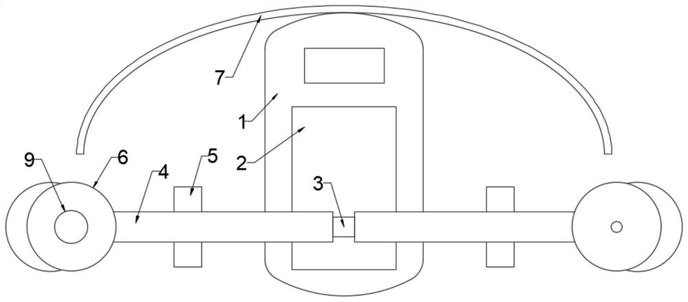
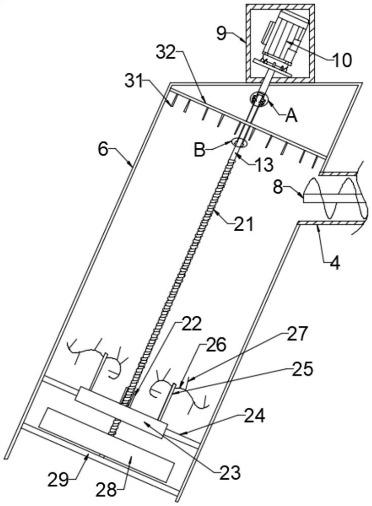
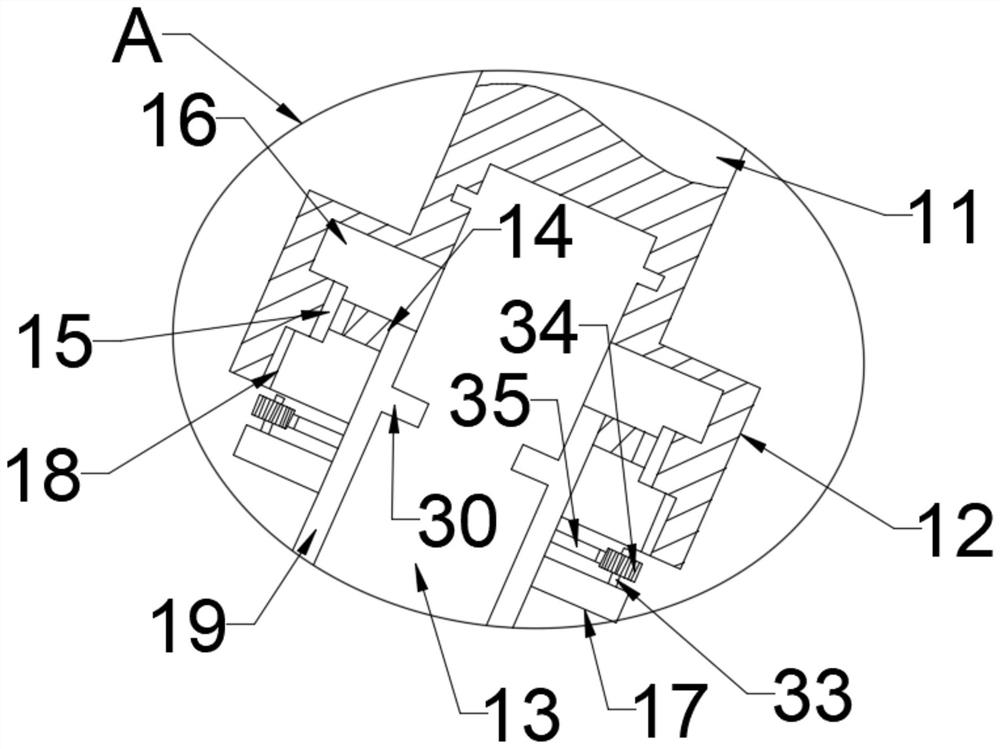
[0028] see Figure 1-5 , a marine floating garbage collection equipment, comprising a hull 1, the front end of the hull 1 is fixedly connected with an arc-shaped baffle 7, the hull 1 is provided with a garbage tank 2, and the upper end of the garbage tank 2 is provided with a first drive box 3, the second The two sides of a drive box 3 are provided with symmetrically distributed transport mechanisms, each of which is connected to a catch box 6, and the shell of the catch box 6 immersed in water is provided with evenly distributed hollow grooves to facilitate the entry of garbage into the catch box 6 Inside, the axis of the inner cavity of the fishing box 6 is provided with a driving rod, and the driving rod is driven to rotate through the second driving box 9 arranged on the fishing box 6. The lower end of the driving rod is provided with a fishing mechanism. When the hull 1 starts At this time, the garbage in front of the arc-shaped baffle 7 floats along the arc-shaped baffle...

Embodiment 2

[0038] This embodiment is expanded on the basis of Embodiment 1. The inner wall of the upper end of the fishing box 6 is fixedly connected with a blade mounting plate 32, and the blade mounting plate 32 is provided with a through hole for the third drive shaft 13 to pass through. 32 lower ends are fixedly connected with evenly distributed cutting blades 31, and the rubbish entangled on the fishing rod 26 can be cut by the cutting blades 31, making it easier to come off and leave the fishing rod 26 to be dropped in the auger box 4.

[0039] To sum up, when the hull 1 starts, the garbage in front of the arc-shaped baffle 7 floats along the arc-shaped baffle 7 to both sides, just at the catch box 6, and the servo motor 10 drives the first drive shaft 11 to rotate , the first drive shaft 11 drives the second drive shaft 12 to drive the third drive shaft 13 to rotate, the third drive shaft 13 drives the screw 21 to rotate, the screw 21 drives the stirring plate 28 to rotate, the sti...


PUM


Abstract

The invention discloses a marine floating garbage collection device, and relates to the field of environmental protection related equipment. The marine floating garbage collection device comprises a ship body, wherein the front end of the ship body is fixedly connected with an arc-shaped baffle plate; the ship body is provided with a garbage groove; a first driving box is arranged at the upper end of the garbage groove; symmetrically distributed transportation mechanisms are arranged on two sides of the first driving box; each transportation mechanism is connected with a fishing box; hollow grooves which are uniformly distributed are formed in a shell, which is immersed in water, of each fishing box, so that garbage can conveniently enter the fishing box; a driving rod is arranged at the axis of an inner cavity of each fishing box; each driving rod is driven to rotate by a second driving box arranged on the corresponding fishing box; and a fishing mechanism is arranged at the lower end of each driving rod. The marine floating garbage collection device is skillful in structure; automatic fishing is realized in the whole process; the labor is saved; and various problems caused by manual fishing are solved.

Description

technical field [0001] The invention relates to the field of equipment related to environmental protection, in particular to a collection equipment for marine floating garbage. Background technique [0002] Marine litter refers to persistent, man-made or processed solid waste in the marine and coastal environment. Marine litter affects the ocean landscape, threatens the safety of navigation, and affects the health of the marine ecosystem, which in turn has a negative effect on the marine economy. [0003] Most of the existing marine debris cleaning is manual salvage, which is time-consuming and labor-intensive, and the efficiency is low, which is not conducive to large-scale use. Moreover, people who stand on the side of the ship for a long time to salvage work are very prone to fatigue and various dangers. Contents of the invention [0004] The object of the present invention is to provide a marine floating garbage collection device to solve the problems raised in the ab...

Claims


Application Information

Patent Timeline
Patent Type & Authority Applications(China)
IPC IPC(8): E02B15/10
CPCE02B15/10
Inventor 陈艳
Owner 陈艳
Why Eureka
Try Eureka