
Novel steel pipe concrete column combined joint and construction method thereof

A technology of concrete-filled steel tubular columns and combined nodes, which is applied in the direction of construction and building structure, can solve the problems of difficult construction, great influence of human operation technology on construction quality and appearance, etc., and achieves convenient production process and installation process. The effect of reducing the difficulty of welding operation and convenient installation

Pending Publication Date: 2021-05-28
渝建建筑科技集团有限公司
View PDF0 Cites 1 Cited by
  • Summary
  • Abstract
  • Description
  • Claims
  • Application Information

AI Technical Summary

Problems solved by technology

[0004] Aiming at the above-mentioned deficiencies existing in the prior art, the purpose of the present invention is to provide a new composite joint of steel pipe concrete columns to solve the difficulty in construction of the steel pipe columns and steel beam joints using short beams or steel corbels in the prior art. Strong members located outside the joints affect the appearance, and human operation technology has a great influence on the construction quality

Method used


Image

  • Novel steel pipe concrete column combined joint and construction method thereof
  • Novel steel pipe concrete column combined joint and construction method thereof
  • Novel steel pipe concrete column combined joint and construction method thereof

Examples


Embodiment Construction

[0027] The present invention will be further described below in conjunction with the accompanying drawings and embodiments.

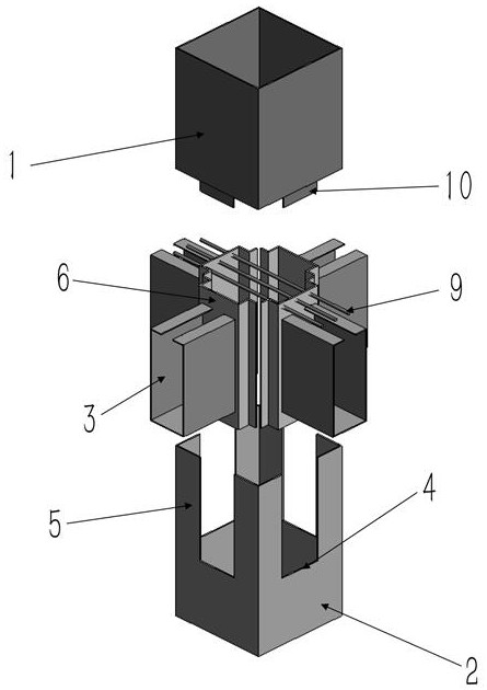
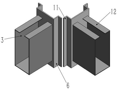
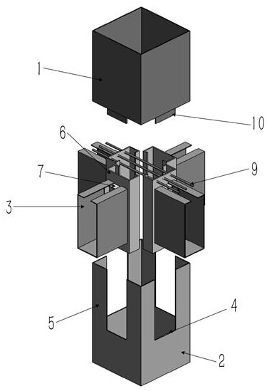
[0028] A new composite joint of concrete filled steel tube columns, see figure 1 , including vertically arranged upper steel pipe columns 1 and lower steel pipe columns 2, and a plurality of U-shaped steel beams 3, the upper edges of the two side walls of the steel beams are respectively bent and extended to form an upper flange 12, A slot 4 is provided on the side wall of the lower steel pipe column, and the slot extends downward from the upper end of the lower steel pipe column, and a connecting end 5 is formed on both sides thereof, and one end of the steel beam passes through the slot and then extends into the lower In the steel pipe column, it is connected with a vertical end plate 6, and the two sides of the end plate are fixedly connected with the connection ends on both sides of the slot; the upper steel pipe column is located above the lower st...


PUM


Abstract

The invention discloses a novel steel pipe concrete column combined joint and a construction method thereof. The novel steel pipe concrete column combined joint comprises an upper steel pipe column, a lower steel pipe column and a plurality of U-shaped steel beams, wherein the upper steel pipe column and the lower steel pipe column are vertically arranged; an open groove is formed in the side wall of the lower steel pipe column and extends downwards from the upper end of the lower steel pipe column, and the two sides of the open groove form connecting ends correspondingly; one end of each steel beam penetrates through the open groove, then extends into the lower steel pipe column and is connected with a vertically-arranged end plate; the two sides of the end plate are fixedly connected with the connecting ends on the two sides of the open groove; the upper steel pipe column is located above the lower steel pipe column, and the lower end of the upper steel pipe column is fixedly connected with the upper end of the upper steel pipe column; and meanwhile, the upper steel pipe column is fixedly connected with the end plate. According to the novel steel pipe concrete column combined joint and the construction method thereof, the end plate is used for reinforcing the joint of the steel pipe columns and the steel beams from the interior, and a reinforcing component is arranged at the joint for further reinforcing, so that the appearance of the joint of the steel pipe columns and the steel beams is smooth, and redundant decoration construction is not needed; and meanwhile, the reinforcing effect of the reinforcing component on the joint is better, and the safety of the joint is higher.

Description

technical field [0001] The invention relates to the technical field of prefabricated building structures, in particular to a novel steel tube concrete column composite node and a construction method thereof. Background technique [0002] The industrialization of construction has always been the development direction advocated by our country and the fundamental way to develop prefabricated buildings. Entering the new era, with the advancement of construction technology and the rapid development of information technology, it is possible to truly realize the industrialization of construction. Prefabricated buildings are buildings built with new industrialized construction methods. Prefabricated buildings can be divided into three categories according to their material forms: prefabricated prefabricated concrete structures, fabricated steel structures and fabricated wood structures. At present, my country is vigorously promoting the development of steel-structured prefabricated ...

Claims


Application Information

Patent Timeline
Patent Type & Authority Applications(China)
IPC IPC(8): E04B1/58E04B1/30
CPCE04B1/185E04B1/30
Inventor 陈琨江世永邹航陈杰张振勇
Owner 渝建建筑科技集团有限公司
Learn More