
Climbing device of construction machinery

A kind of construction machinery and unified technology, applied in the direction of construction, building structure, scaffolding accessories, etc., can solve the problems of manual lifting to high places, achieve the effect of improving speed and safety, and increasing the force-bearing area

Inactive Publication Date: 2021-05-28
马鞍山量子线自动化科技有限公司
View PDF0 Cites 1 Cited by
  • Summary
  • Abstract
  • Description
  • Claims
  • Application Information

AI Technical Summary

Problems solved by technology

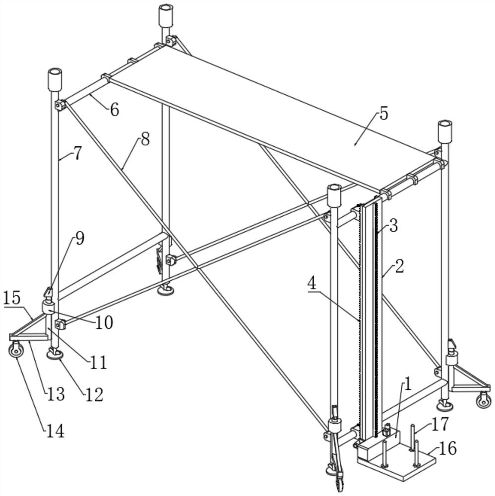
[0005] Aiming at the deficiencies of the prior art, the present invention provides a climbing device for construction machinery, which can facilitate the installation of the climbing device on the construction scaffolding to carry building materials, and is also convenient for construction workers to go up and down the scaffold, reducing the labor intensity of the construction workers. Compared with the advantages of safety, it solves the problem that construction materials also need to be manually lifted to a high place by construction personnel, or the construction personnel reciprocate down to the ground and transported to the scaffolding construction platform.

Method used


Image

  • Climbing device of construction machinery
  • Climbing device of construction machinery
  • Climbing device of construction machinery

Examples


Embodiment 1

[0030] A climbing device for construction machinery, comprising four standpipes 7, four cross bars 6, two spacer frames 8 and vertically arranged support plates 2, the two spacer frames 8 are connected to the same vertical plane by bolts The pipe walls of the two vertical pipes 7 on the top are firmly connected, and the two ends of the two cross bars 6 are respectively fixedly connected with the pipe walls of the two vertical pipes 7 on the same vertical plane, and the two horizontal pipes on the same horizontal plane The rod 6 is connected with a construction platform 5 together, and the left end of the support plate 2 is fixedly connected with a fixed block 30 on the upper and lower sides. The upper end of block 32 is all fixedly connected with the side wall of support plate 2 by connecting block, and the side wall of fixed block 30 is fixedly connected with the bar wall of cross bar 6 by through hole, and the upper end of fixed block 30 is connected with fixed mechanism, and...

Embodiment 2

[0032] Embodiment 2: the difference based on Embodiment 1 is;

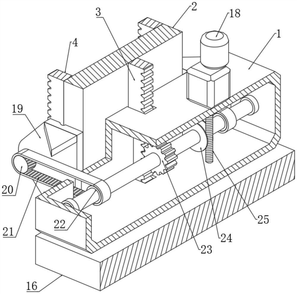
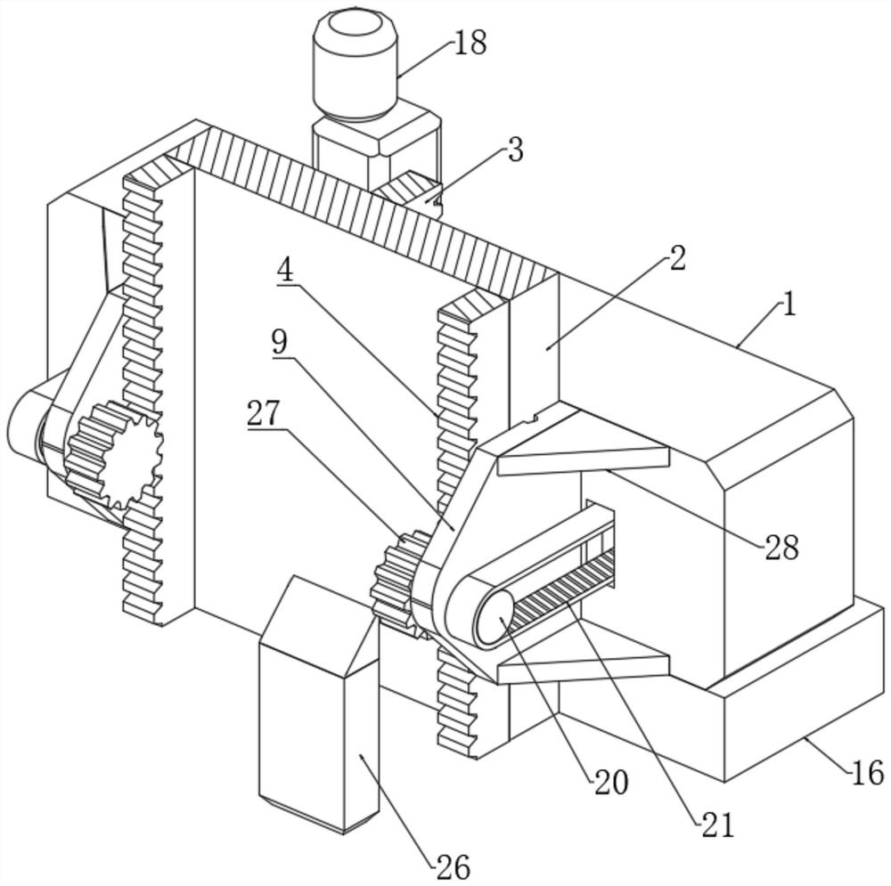
[0033] The climbing mechanism includes a rotating shaft connected in the box body 1 through the first rolling bearing. The shaft wall of the rotating shaft is fixedly connected with the first ring gear 23, the ring gear 23 meshes with the first rack 3, and the shaft wall of the rotating shaft is fixedly connected with a A turbine 24, one side of the turbine 24 is meshed with a worm 25, the upper end of the casing 1 is fixedly connected with a geared motor 18, the output shaft of the geared motor 18 runs through the side wall of the casing 1 and is fixedly connected with the upper end of the worm 25 coaxially, The opposite sides of the support plate 2 are slidingly connected with the mounting plate 19, and the right ends of the two mounting plates 19 are fixedly connected with the side wall of the box body 1, and the side wall of the support plate 2 away from the box body 1 is fixedly connected with two second The ...

Embodiment 3

[0035] Embodiment 3: the difference based on embodiment 1 is;

[0036] The fixing mechanism includes a rectangular rod 35 arranged in parallel on the top of the fixed block 30, the lower rod wall of the rectangular rod 35 is fixedly connected with the upper end of the fixed block 30 through two connecting rods, the rod wall of the rectangular rod 35 is slidably sleeved with a spring 34, One end of the spring 34 is fixedly connected with the rod wall of one of the connecting rods, the other end of the spring 34 is fixedly connected with a rectangular block, one side of the rectangular block is slidably connected with the rod wall of the rectangular rod 35 through a square hole, and one side of the rectangular block is fixed Connected with a triangular block 31, one side of the triangular block 31 is clamped with a positioning block 33, and the two ends of the positioning block 33 are fixedly connected with the two clamping blocks 32 on the fixed block 30 respectively, and the en...


PUM


Abstract

The invention relates to the technical field of construction machinery, and discloses a climbing device of construction machinery. The climbing device comprises four vertical pipes, four transverse rods, two limiting frames and a vertically-arranged supporting plate, wherein the two limiting frames are connected with the pipe walls of the two vertical pipes on the same vertical face in a fastened mode through bolts; the two ends of the two transverse rods are fixedly connected with the pipe walls of the two vertical pipes on the same vertical face correspondingly; the two transverse rods on the same horizontal plane are jointly connected with a construction table in an erected mode; the upper side and the lower side of the left end of the supporting plate are fixedly connected with fixing blocks correspondingly; and the upper ends of the fixing blocks are connected with two clamping blocks of triangular structures in a clamped mode through clamping grooves. According to the climbing device of the construction machinery, construction personnel can conveniently and rapidly carry construction materials onto the construction machinery, the construction personnel do not need to carry the construction materials manually in the construction process, the construction personnel can conveniently get on and off a scaffold, the labor intensity of the construction personnel is relieved, the construction process is safe, and meanwhile the climbing device is convenient and rapid to mount.

Description

technical field [0001] The invention relates to the technical field of construction machinery, in particular to a climbing device for construction machinery. Background technique [0002] Construction machinery is the general term for mechanical equipment used in engineering construction and urban and rural construction. With the development of the construction industry, the degree of construction mechanization is increasing year by year. The continuous development of construction mechanization has promoted the reform of construction technology, the emergence of high-rise buildings, the promotion of new technology construction, and promoted the further development of construction mechanization, mainly by excavation machinery, shovel transport machinery, compaction machinery, engineering Heavy machinery, piling machinery, road machinery, concrete machinery, concrete product machinery, steel grade prestressed machinery, decoration machinery, aerial work scaffolding and other m...

Claims


Application Information

Patent Timeline
IPC IPC(8): E04G1/24E04G5/00E04G5/02
CPCE04G1/24E04G5/00E04G5/02E04G2001/242E04G2005/008
Inventor 刘东项敏霞
Owner 马鞍山量子线自动化科技有限公司
Learn More