Synchronizer ring mechanism

A technology of synchronizer and gear ring, which is applied in the field of gear ring mechanism and can solve the problems of high cost

Pending Publication Date: 2021-05-28
CHONGQING TSINGSHAN IND
View PDF0 Cites 1 Cited by
  • Summary
  • Abstract
  • Description
  • Claims
  • Application Information

AI Technical Summary

Problems solved by technology

[0007] Although the current multi-cone synchronizer gear ring mechanism m

Method used


Image

  • Synchronizer ring mechanism
  • Synchronizer ring mechanism
  • Synchronizer ring mechanism

Examples


Embodiment Construction

[0026] An embodiment of the gear ring mechanism of the synchronizer of the present invention:

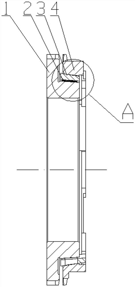
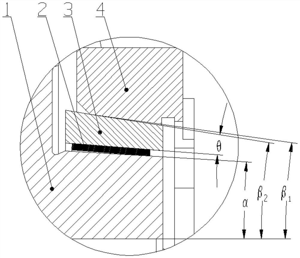
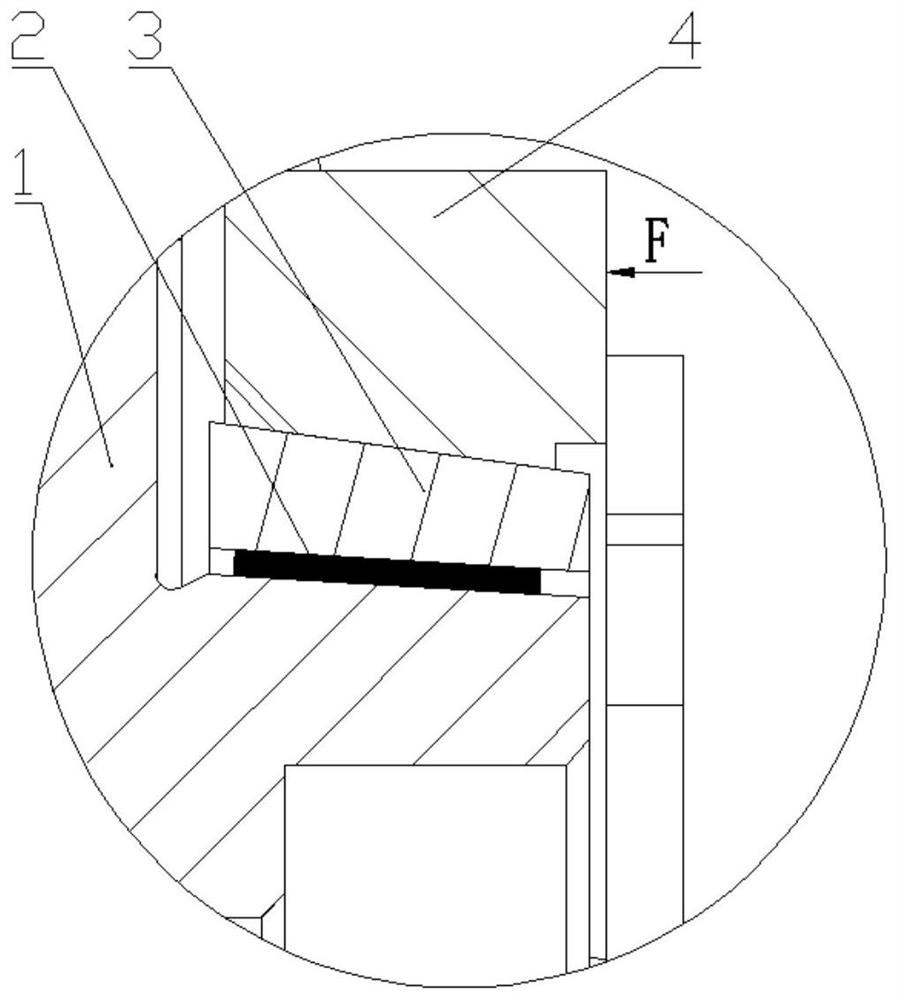
[0027]see Figure 1-Figure 7 , a gear ring mechanism of a synchronizer, comprising a combination tooth (1), a synchronizer lock ring (4), a cone ring (3), a plurality of friction plates (2), the shaft of the synchronizer lock ring (4) The hole is a tapered hole, the coupling tooth (1) is provided with an axially extending conical boss (5), and the tapered ring (3) is set on the conical boss (5) of the coupling tooth (1) , and the cone ring (3) is located between the outer cone surface of the conical boss (5) of the coupling tooth (1) and the inner cone surface of the synchronizer lock ring (4), and the friction plate (2) is fixedly connected to the On the inner tapered surface of the cone ring (3); the included angle β between the outer tapered surface of the cone ring (3) and the central axis 2 Greater than the angle β between the inner tapered surface of the synchronizer lock ri...


PUM

PropertyMeasurementUnit
Angleaaaaaaaaaa
Angleaaaaaaaaaa

Abstract

The invention discloses a synchronizer ring mechanism. The synchronizer ring mechanism comprises a combined gear, a synchronizer locking ring, a conical ring and a plurality of friction plates, a shaft hole of the synchronizer locking ring is a conical hole, a conical boss is arranged on the combined gear, the conical ring is located on the conical boss and located between the outer conical surface of the conical boss of the combined gear and the inner conical surface of the synchronizer locking ring, and the friction plates are fixedly connected to the inner conical surface of the conical ring; the included angle beta 2 between the outer conical surface of the conical ring and the central axis is larger than the included angle beta 1 between the inner conical surface of the synchronizer locking ring and the central axis, the large end of the inner conical surface of the synchronizer locking ring makes contact with the large end of the outer conical surface of the conical ring, the included angle between the inner conical surface of the conical ring and the central axis is larger than the included angle alpha between the outer conical surface of the combined gear and the central axis, and the small end of the inner conical surface of the conical ring makes contact with the small end of the outer conical surface of the combined gear; and a plurality of open grooves are formed in the large-diameter end of the conical ring, a plurality of limiting bosses extending along a gen are arranged at the small end of the conical ring, a plurality of limiting blocks extending in the radial direction are arranged at the small end of the synchronizer locking ring, and a limiting groove is formed between every two adjacent limiting blocks and used for allowing the corresponding limiting boss to be inserted therein.

Description

technical field [0001] The invention relates to the field of automobile transmissions, in particular to a ring gear mechanism of a synchronizer. Background technique [0002] The synchronous structure of the automobile synchronizer is a mechanical device that enables the car to shift gears smoothly. In order to ensure that some gears such as 1st gear, 2nd gear, reverse gear or even 3rd gear and 4th gear are easily and smoothly shifted during the operation of the vehicle, these gears are often designed as a double-cone synchronizer ring mechanism, or even three gears. Cone synchronizer gear ring mechanism. [0003] see Figure 6 , in the existing double-cone synchronizer gear ring mechanism, it generally includes a combination tooth (1a), an inner ring (5a), a cone ring (3a), a synchronizer lock ring (4a), and two friction plates (2a), The synchronizer lock ring (4a) and the inner ring (5a) rotate synchronously, and the combined teeth (1a) and the cone ring (3a) rotate sync...

Claims


Application Information

Patent Timeline
IPC IPC(8): F16D23/04
CPCF16D23/025F16D23/04
Inventor 唐满荣陈超超陈理王文波黄虎
Owner CHONGQING TSINGSHAN IND
Why Eureka
Try Eureka