A transmission for plant protection machinery

A transmission and transmission housing technology, which is applied in mechanical equipment, vehicle transmissions, gear transmissions, etc., can solve the problems of gear arrangement not conforming to work habits, inconvenient operation by staff, and inability to meet usage requirements, etc. The gear arrangement is clear and reasonable, the effect of avoiding disengagement and random gearing, and reducing the processing cost

Active Publication Date: 2017-03-08
山东卫禾传动股份有限公司
View PDF9 Cites 0 Cited by
  • Summary
  • Abstract
  • Description
  • Claims
  • Application Information

AI Technical Summary

Problems solved by technology

[0002] The existing plant protection machinery in the domestic market is mainly imported from abroad, and the matching gearbox has the following defects: 1) There are many gears, and foreign matching gearboxes generally have 9-12 gears, which makes it very inconvenient for the staff to operate; 2 ) The shifting force of foreign matching gearboxes is relatively heavy, and the staff will feel very tired after a long time; 3) Foreign matching gearboxes mainly use bevel gear meshing, which makes the gearbox difficult to process, high in production costs, and low in gear transmission efficiency; 4 ) The gear arrangement of foreign matching gearboxes does not conform to the working habits of domestic staff, so that staff often have misoperations in the process of operation, and there are out-of-gear or disordered gears; 5) The speed ratio span of foreign matching gearboxes is small , can not meet the use requirements under various working conditions; 6) foreign matching gearbox clutch adopts multi-plate clutch, the transmission torque is small, or the separation force is heavy, and they are all installed on one shaft, so the layout space is small

Method used


Image

  • A transmission for plant protection machinery
  • A transmission for plant protection machinery
  • A transmission for plant protection machinery

Examples


Embodiment 1

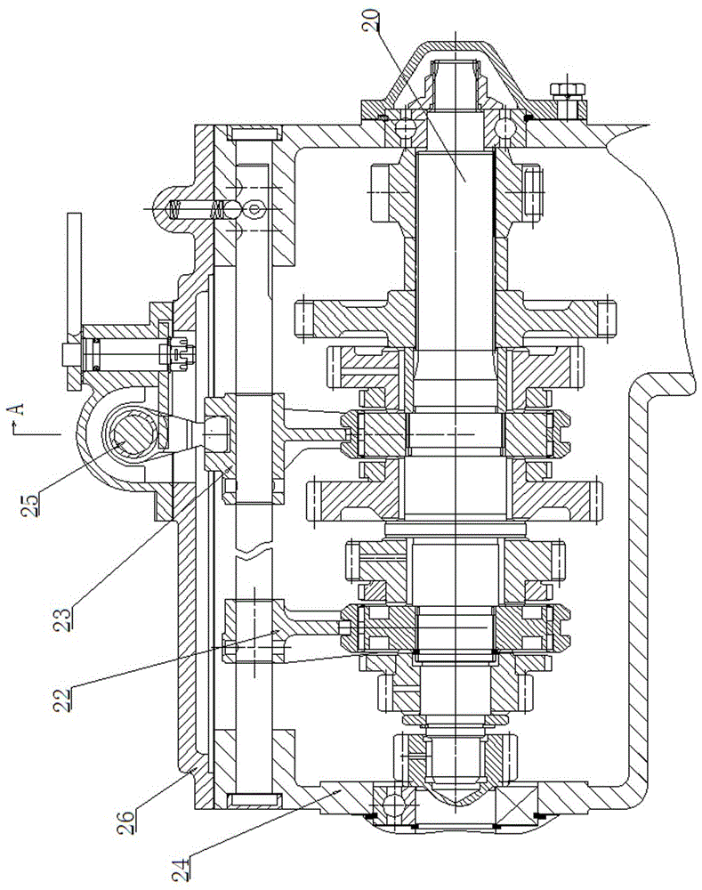
[0047]The speed changer for plant protection machinery includes a speed change case 24 with a loam cake 26 installed on the top, and one shaft 2, two shafts 6, three shafts 20, reverse gear idler shaft 7 and output shaft 19 installed in the speed change case 24, one Shaft 2 is a gear shaft, its outer end is connected to input flange 1, and input flange 1 is connected to engine clutch assembly through transmission shaft 45. Engine clutch assembly includes: clutch housing 38, clutch shaft 39, clutch dial shaft 41 and clutch Output flange 40, clutch shaft 39 is installed in the body of clutch case 38 by clutch sleeve seat 37, the output end of clutch shaft 39 is connected with transmission shaft 45 by clutch output flange 40, and one end of clutch shaft 39 in clutch case 38 body is from the left Connecting disc 34, clutch driven disc 35 and clutch driving disc 36 are installed to the right, and release bearing 43 and release bearing seat 44 are installed outside the clutch cover s...

Embodiment 2

[0066] The speed changer for plant protection machinery includes a speed change case 24 with a loam cake 26 installed on the top, and one shaft 2, two shafts 6, three shafts 20, reverse gear idler shaft 7 and output shaft 19 installed in the speed change case 24, one Shaft 2 is a gear shaft, its outer end is connected to input flange 1, and input flange 1 is connected to engine clutch assembly through transmission shaft 45. Engine clutch assembly includes: clutch housing 38, clutch shaft 39, clutch dial shaft 41 and clutch Output flange 40, clutch shaft 39 is installed in the body of clutch case 38 by clutch sleeve seat 37, the output end of clutch shaft 39 is connected with transmission shaft 45 by clutch output flange 40, and one end of clutch shaft 39 in clutch case 38 body is from the left Connecting disc 34, clutch driven disc 35 and clutch driving disc 36 are installed to the right, and release bearing 43 and release bearing seat 44 are installed outside the clutch cover ...


PUM


Abstract

The invention discloses a transmission for plant protection machinery. The transmission comprises a transmission casing provided with an upper cover at the top as well as a shaft I, a shaft II, a shaft III, a reverse gear idler shaft and an output shaft which are mounted in the transmission casing, wherein the shaft I is a gear shaft, an input flange is connected with the outer end of the shaft I and connected with an engine clutch assembly through a transmission shaft, the other end of the shaft I is connected with the shaft III through a needle roller bearing, the shaft II is mounted right below the shaft III, the reverse gear idler shaft is mounted right above the shaft III, the output shaft is arranged under the shaft III, and a first reverse gear shift shaft, a second-gear and third-gear fork shaft and a gear shift mechanism assembly are arranged above the shaft III; and a high-low gear fork shaft is arranged left above the output shaft. Compared with the prior art, the transmission for the plant protection machinery has the characteristics of a few gears, high operation efficiency, small gear shifting force and the like, the processing difficulty is effectively reduced, the transmission efficiency is improved, further, the gear distribution is reasonable, and gear separation and disorder are effectively avoided.

Description

technical field [0001] The invention relates to the technical field of motor vehicle transmissions, in particular to a transmission for plant protection machinery. Background technique [0002] The existing plant protection machinery in the domestic market is mainly imported from abroad, and the matching gearbox has the following defects: 1) There are many gears, and foreign matching gearboxes generally have 9-12 gears, which makes it very inconvenient for the staff to operate; 2 ) The shifting force of foreign matching gearboxes is relatively heavy, and the staff will feel very tired after a long time; 3) Foreign matching gearboxes mainly use bevel gear meshing, which makes the gearbox difficult to process, high in production costs, and low in gear transmission efficiency; 4 ) The gear arrangement of foreign matching gearboxes does not conform to the working habits of domestic staff, so that staff often have misoperations in the process of operation, and there are out-of-ge...

Claims


Application Information

Patent Timeline
Patent Type & Authority Patents(China)
IPC IPC(8): F16H57/023F16H3/08
CPCF16H3/093F16H57/023F16H2003/0818F16H2057/02069F16H2200/0052F16H2200/0086
Inventor 张志东吴伟王学良彭玉兰马卫东肖振兴宋全美赵成栋
Owner 山东卫禾传动股份有限公司
Why Eureka
Try Eureka