
HST hydraulic mechanical variable-speed drive axle for agricultural harvesting machine

A technology of harvesting machinery and hydraulic machinery, applied in agricultural machinery and implements, agriculture, harvesters, etc., can solve problems such as weak walking, frequent replacement of clutch assemblies, difficulty in gearing gears, and high prices

Pending Publication Date: 2021-09-14
SHANDONG JUMING MASCH CO LTD
View PDF8 Cites 0 Cited by
  • Summary
  • Abstract
  • Description
  • Claims
  • Application Information

AI Technical Summary

Problems solved by technology

When the mechanical clutch assembly transaxle is matched with the harvester, the gearbox often has the phenomenon of difficulty in gearing, walking weakness, and frequent replacement of the clutch assembly; when the harvester is matched with the single-motor hydrostatic transaxle, although the speed change The box often has problems such as difficulty in gear shifting, weak walking and frequent replacement of the clutch assembly. However, with pure hydrostatic transmission, the hydraulic system bears a large load for a long time, and the entire circuit will generate a lot of heat, which will increase the temperature of the hydraulic oil. Various failures will inevitably occur; when the HMT hydraulic continuously variable transmission drive axle is matched with the harvester, it can realize the mechanical stepless speed change and improve the walking efficiency of the machine, but the price of the whole machine is too high, and the maintenance cost in the later period is also very high. The fuel consumption is high, and the enthusiasm of agricultural machinery users is not high

Method used


Image

  • HST hydraulic mechanical variable-speed drive axle for agricultural harvesting machine
  • HST hydraulic mechanical variable-speed drive axle for agricultural harvesting machine
  • HST hydraulic mechanical variable-speed drive axle for agricultural harvesting machine

Examples


Embodiment Construction

[0037] In order to more clearly and clearly illustrate the specific implementation objectives and implementation modes of the present invention, the technical solution of the present invention will be fully described below, and the described embodiments are part of the embodiments of the present invention, rather than all embodiments. On the premise of no creative work, all other embodiments based on the described embodiments of the present invention belong to the protection scope of the present invention.

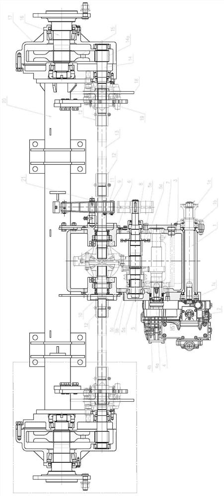
[0038] A kind of HST hydraulic mechanical transaxle for agricultural harvesting machinery of the present invention, such as figure 1 shown, including:

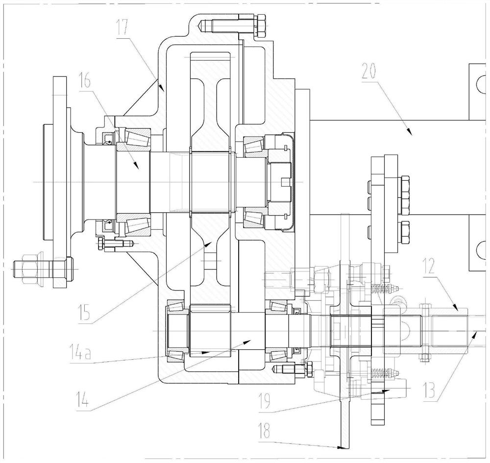
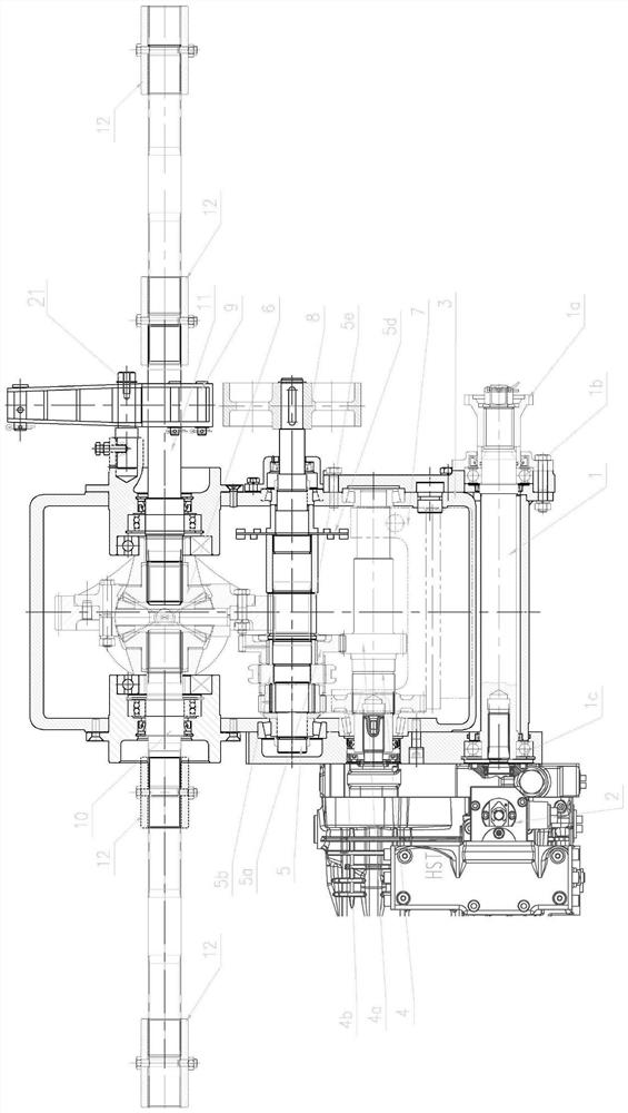
[0039] The gearbox 3 and the bridge welded beam 20 fixedly connected to each other, such as figure 1 , figure 2 As shown, a differential assembly 6 is installed inside the gearbox 3 , and a left half shaft 10 and a right half shaft 11 are coaxially arranged on both sides of the differential assembly 6 . The ends of the...


PUM


Abstract

The invention relates to an HST hydraulic mechanical variable-speed drive axle for agricultural harvesting machine. The HST hydraulic mechanical variable-speed drive axle comprises a gearbox, a bridge welding beam, a left reduction assembly and a right reduction assembly. A differential assembly connected with a left half shaft and a right half shaft is arranged in the gearbox, and the tail end of the left half shaft and the tail end of the right half shaft are sequentially connected with a transition shaft, a brake disc, a brake caliper assembly and an edge reduction assembly. The edge reduction assembly comprises an edge reduction flange shaft, an edge reduction input shaft and a tail end transmission large gear. An input shaft, a main shaft, a middle shaft and an oil supporting disc are arranged in the gearbox, and an HST device and a brake shaft are arranged on two sides of the gearbox. According to the HST hydraulic mechanical variable-speed drive axle for the agricultural harvesting machine, gear shifting is controlled through one rod, so that the walking efficiency is improved, the performance is reliable, the cost performance is high, and the multi-aspect requirements of agricultural machinery households are met.

Description

technical field [0001] The invention relates to the technical field of travel transmissions for motor vehicles, in particular to an HST hydraulic mechanical transmission drive axle for agricultural harvesting machinery. Background technique [0002] The existing agricultural harvesting mechanical drive axles in the domestic market are mainly divided into mechanical clutch assembly transaxles, single-motor hydrostatic hydraulic transaxles, and HMT hydraulic stepless variable speed drive axles. When the mechanical clutch assembly transaxle is matched with the harvester, the gearbox often has the phenomenon of difficulty in gearing, walking weakness, and frequent replacement of the clutch assembly; when the harvester is matched with the single-motor hydrostatic transaxle, although the speed change The box often has problems such as difficulty in gear shifting, weak walking and frequent replacement of the clutch assembly. However, with pure hydrostatic transmission, the hydrauli...

Claims


Application Information

Patent Timeline
IPC IPC(8): F16H47/02F16H57/023A01D69/06A01D69/03B60K17/08B60K17/16B60T1/06
CPCF16H47/02F16H57/023B60K17/08A01D69/06A01D69/03A01D69/005B60K17/165B60T1/065
Inventor 邵强高奎增齐金财
Owner SHANDONG JUMING MASCH CO LTD
Learn More