Pipeline heat tracing device

A thermal device and pipeline technology, applied in pipeline protection, protection of pipelines through thermal insulation, heat exchange equipment, etc., can solve the problems of low installation accuracy, huge device volume, low installation efficiency, etc., and achieve weight reduction and cost reduction. , The effect of uniform tightening force

Pending Publication Date: 2021-05-28
徐正强
View PDF0 Cites 1 Cited by
  • Summary
  • Abstract
  • Description
  • Claims
  • Application Information

AI Technical Summary

Problems solved by technology

[0008] The purpose of the present invention is to provide a pipe heat tracing device to solve the problems of poor heat tracing effect of traditional heat tracing devices, too large device volume, low installation accuracy and low installation efficiency at the heat tracing construction site

Method used


Image

  • Pipeline heat tracing device
  • Pipeline heat tracing device

Examples


Embodiment Construction

[0017] The present invention will be described in further detail below: the present embodiment is implemented on the premise of the technical solution of the present invention, and detailed implementation is provided, but the protection scope of the present invention is not limited to the following examples.

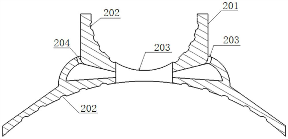
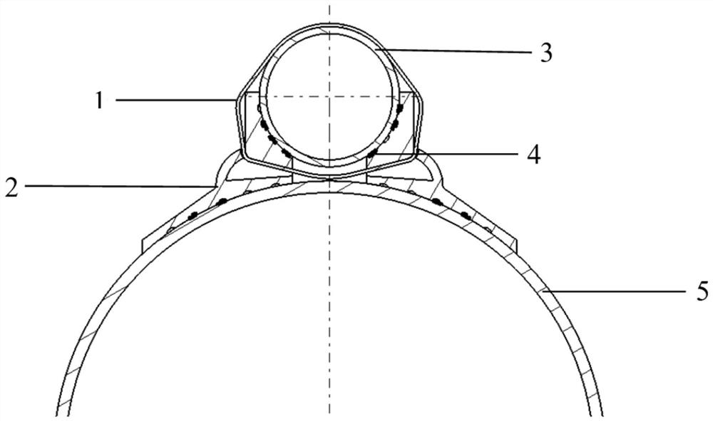
[0018] Such as figure 1 and 2 As shown, the pipe heating device 2 is arranged between the heating pipe 3 and the heated pipe 5, and is closely attached to the two; the outer surface of the pipe heating device 2 is provided with a convex structure 201, and There is a reserved hole 203 for the metal strap 1 to pass through; there is a stress point 204 between the convex structure 201 and the metal strap 1, and the convex structure 201 squeezed by force is between the metal strap 1 and the stressed Under the synergistic effect of the force points 204, local deformation occurs, so that the pipeline heating device 2 and the heating pipeline 3 are tightly connected and closel...


PUM


Abstract

The invention relates to a pipeline heat tracing device which is arranged between a heat tracing pipeline and a heat-traced pipeline and tightly attached to the heat tracing pipeline and the heat-traced pipeline. According to the pipeline heat tracing device, the heat tracing device and the heat tracing pipe are fastened through a metal binding belt so that the fastening force between the heat tracing pipe and the heat tracing device is more uniform, the installation is more convenient, slight deformation can be conducted while the strength is guaranteed, the heat tracing device and the heat tracing pipe are perfectly attached, heat cannot be lost in the heat transfer process, and the heat tracing effect is achieved. The self weight of the pipeline heat tracing device is reduced structurally, and the cost is reduced. The pipeline heat tracing device has a clear on-site installation standard which is completely attached to an acceptance standard.

Description

technical field [0001] The invention relates to the field of pipeline heat tracing, in particular to a pipeline heat tracing device. Background technique [0002] At present, there are mainly two heat tracing methods used in pipeline heat tracing technology: one is to use iron wire to bind the heat tracing pipe and the heated pipe to fix them to achieve the heat tracing effect; the other is to use a heat tracing device to connect the heat tracing The heat pipe and the heated pipe are fastened with bolts to achieve the heat tracing effect. These two heat tracing methods have the following disadvantages: [0003] 1. Binding directly with iron wires leads to the heating pipe and the heated pipe, the contact area is small, basically point contact, and the heat tracing effect cannot be achieved; [0004] 2. The heat tracing device and the heat tracing pipe are fastened with bolts. Although the contact area is increased, it cannot achieve a close fit, resulting in serious heat l...

Claims


Application Information

Patent Timeline
Patent Type & Authority Applications(China)
IPC IPC(8): F16L59/135
CPCF16L59/135
Inventor 徐正强何天翔
Owner 徐正强
Why Eureka
Try Eureka