Data acquisition device based on RFID technology

A data collector and technology, which is applied in the field of data collectors based on RFID technology, can solve the problems of inconvenient collection of data terminals close to items, inconvenient use of hand-held data collectors, and inconvenience to adjust the collection data terminals of data collectors. , to achieve the effect of ensuring stability

Active Publication Date: 2021-05-28
广州佳进智能科技有限公司
View PDF7 Cites 0 Cited by
  • Summary
  • Abstract
  • Description
  • Claims
  • Application Information

AI Technical Summary

Problems solved by technology

[0002] Data collectors or inventory machines and handheld computers have the characteristics of integration, mobility, small size, light weight, high performance, and are suitable for hand-holding. There are also data collectors such as HK9920, HK9900, and C5000W on the market. This type of data collector is mainly used to collect barcode or RFID information. Since it has an operating system, the data collector processes data by itself, and also has mobile data transmission functions such as WIFI, GPRS, and Bluetooth, which can be easily moved or operated outdoors; now Some data collectors are mostly fixed or hand-held. With the rise of the logistics industry, hand-held data collectors are more and more widely used, but the existing hand-held data collectors are inconvenient to use. For example, in logistics management, The user needs to take the adhesive tape, product code, etc. At this time, if the data collector is taken again, the user will be more busy and his hands will be tired, and when the item to be collected is at a higher or lower place, It is inconvenient for the user to bring the data collection end of the data collector close to the object, and it is inconvenient to adjust the orientation of the data collection end of the data collector

Method used


Image

  • Data acquisition device based on RFID technology
  • Data acquisition device based on RFID technology
  • Data acquisition device based on RFID technology

Examples


Embodiment 1

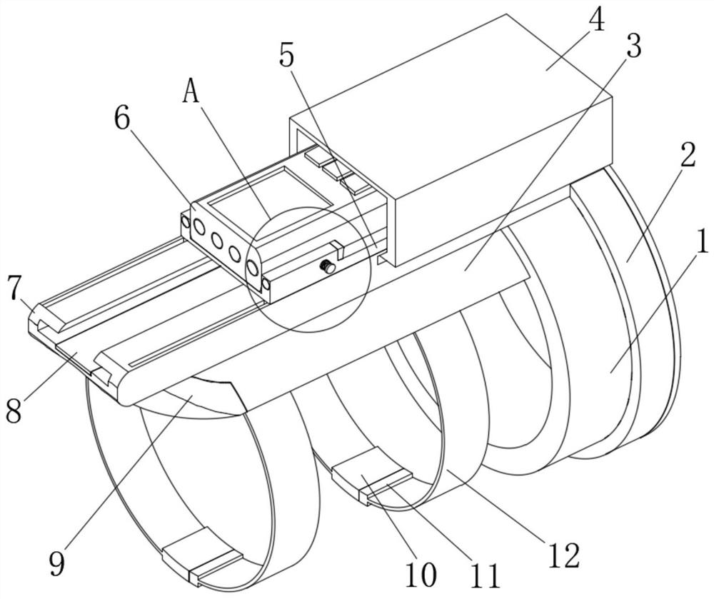
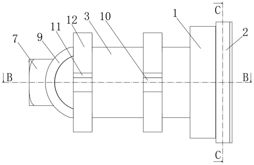
[0027] Embodiment 1: a data collector based on RFID technology, including a fixed ring 1, a support seat 3 and a fixed seat 7;

[0028] Fixed ring 1: the right end is provided with an embedded groove, the upper half of the embedded groove is provided with a spring groove, the lower side of the spring groove is fixed with a spring 21, and the upper end of the spring groove is movably placed with a pressing ball 20 and a spring 21. The upper end is in contact with the side of the lower half of the pressing ball 20, and the inlay groove is rotatably connected with a positioning swivel 2, and the inner side of the positioning swivel 2 is arranged in a circular array with fixed-angle pressing bumps 22, and the pressing ball 20 is arranged in a circular array. The side of the position-adjusting ring 2 is fixed against the side of the pressing bump 22 at a fixed angle. The upper attachment seat 19 is fixed on the side of the upper half of the position-adjusting ring 2, and the positio...

Embodiment 2

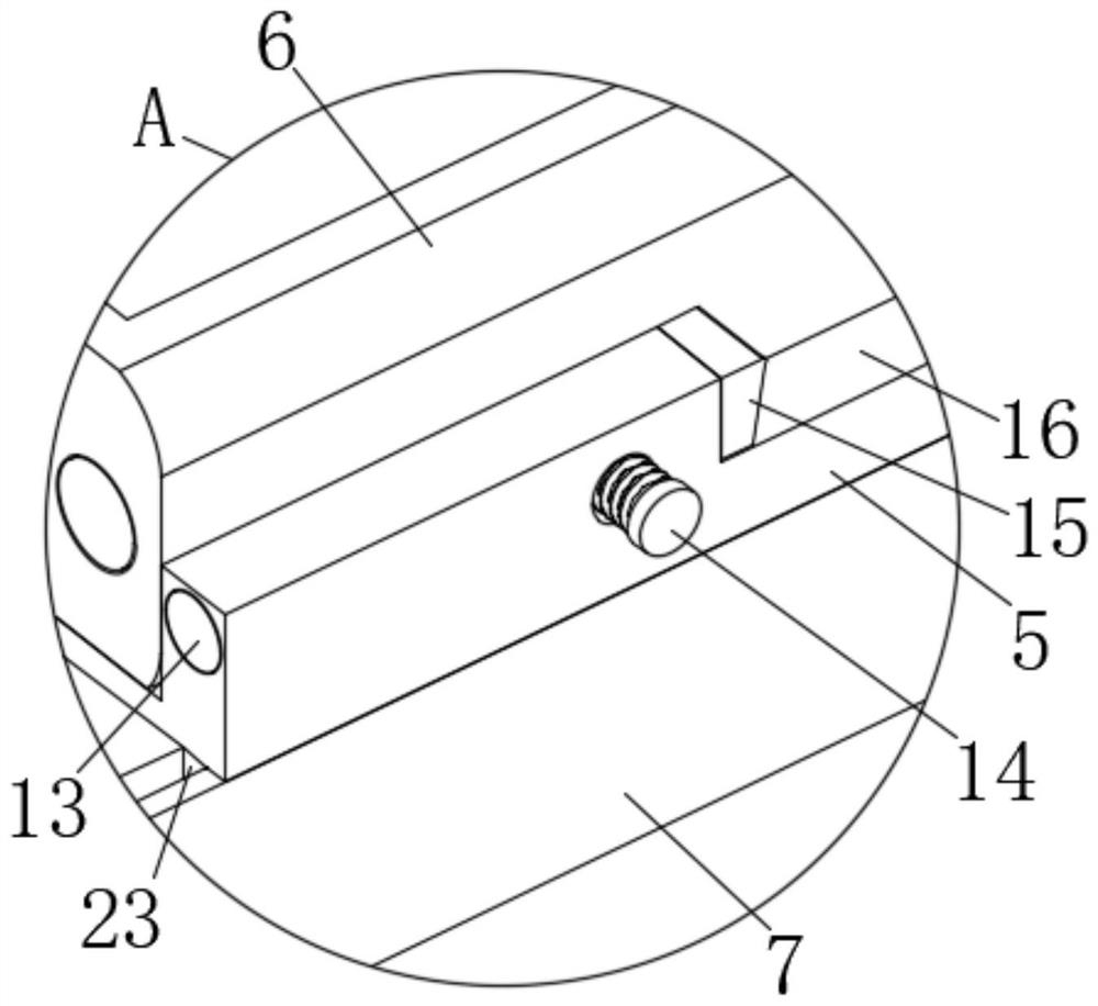
[0032] The difference between this embodiment and Embodiment 1 is that it also includes an adjustment side groove 16, and there are two adjustment side grooves 16, which are respectively arranged on the front and rear ends of the sliding seat 5. The length dimension of the adjustment side groove 16 is Larger than the width of the data collector body 6, the data collector body 6 can be snapped into the side slot 16 to change the orientation of the data collector body 6 to scan the information codes on different sides of the item, and also include There are four elastic rubber pads 15 for clamping, and they are respectively fixed on the left and right sides of the two steering side grooves 16. The data collector body 6 can be clamped and fixed by the elastic rubber pads 15 for clamping, and it also includes There is a pressing screw 14, and the rear end thread of the pressing screw 14 passes through the front side of the sliding seat 5 and collides with the front side of the data...

Embodiment 3

[0034] The difference between this embodiment and embodiment two is:

[0035] In this embodiment, it also includes a cloth-covered cushion 9, the right end of which is fixed on the left end of the support seat 3, and the cloth-covered cushion 9 can prevent the support seat 3 from abrading the user's wrist. Direct illuminating lamp 13, two direct illuminating lamps 13 are interspersed respectively at the front and rear ends of the left side of the sliding seat 5, the output end of the control device in the data collector body 6 is electrically connected to the input end of the direct illuminating lamp 13, through direct illuminating The illuminating lamp 13 is convenient to illuminate the information code of the article when the light is poor, and also includes a limiting rod 23. There are two limiting rods 23 and they are respectively fixed on the lower front and rear ends of the left end of the sliding seat 5, and the limiting rod 23 is movable and interspersed In the limitin...


PUM


Abstract

The invention discloses a data acquisition device based on the RFID technology. The data acquisition device comprises a fixing ring, a supporting seat and a fixing seat. An embedded groove is formed in the right end of the fixing ring, a spring groove is formed in the side face of the upper half portion of the embedded groove, and a spring is fixed to the lower side of the spring groove. An abutting ball is movably placed in the upper end of the spring groove, the upper end of the spring abuts against the side face of the lower half portion of the abutting ball, and a position adjusting rotating ring is rotationally connected into the embedded groove. According to the data acquisition device based on the RFID technology, the data acquisition device can be arranged on the arm in a sleeving mode and is kept fixed, a user can take other objects with the two hands, the hands of the user are prevented from being tired, the position of the data acquisition device and the orientation of a data collecting end can be adjusted according to the needs of the user, and the situation that the data acquisition device hinders the arm of the user is avoided. And moreover, the information of objects at different positions can be collected, and the distance between the data acquisition device and the objects can be adjusted so that the data of the objects located at low positions or high positions can be conveniently collected.

Description

technical field [0001] The invention relates to the technical field of data collectors, in particular to a data collector based on RFID technology. Background technique [0002] Data collectors or inventory machines and handheld computers have the characteristics of integration, mobility, small size, light weight, high performance, and are suitable for hand-holding. There are also data collectors such as HK9920, HK9900, and C5000W on the market. This type of data collector is mainly used to collect barcode or RFID information. Since it has an operating system, the data collector processes data by itself, and also has mobile data transmission functions such as WIFI, GPRS, and Bluetooth, which can be easily moved or operated outdoors; now Some data collectors are mostly fixed or hand-held. With the rise of the logistics industry, hand-held data collectors are more and more widely used, but the existing hand-held data collectors are inconvenient to use. For example, in logistic...

Claims


Application Information

Patent Timeline
Patent Type & Authority Applications(China)
IPC IPC(8): F16M13/04F16M11/04F16M11/16F16M7/00B08B17/04G06K19/00
CPCF16M13/04F16M11/045F16M11/16F16M7/00B08B17/04G06K19/005
Inventor 邱德平吴鉴欣黄旭辉
Owner 广州佳进智能科技有限公司
Why Eureka
Try Eureka