
A data acquisition device based on rfid technology
A data collector and technical technology, applied in the field of data collectors based on RFID technology, can solve the problems of inconvenient collection of data terminals close to objects, inconvenient use of hand-held data collectors, inconvenient adjustment of data collection terminals of data collectors, etc. , to achieve the effect of ensuring the stability of
- Summary
- Abstract
- Description
- Claims
- Application Information
AI Technical Summary
Problems solved by technology
Method used
Image

Examples
Embodiment 1
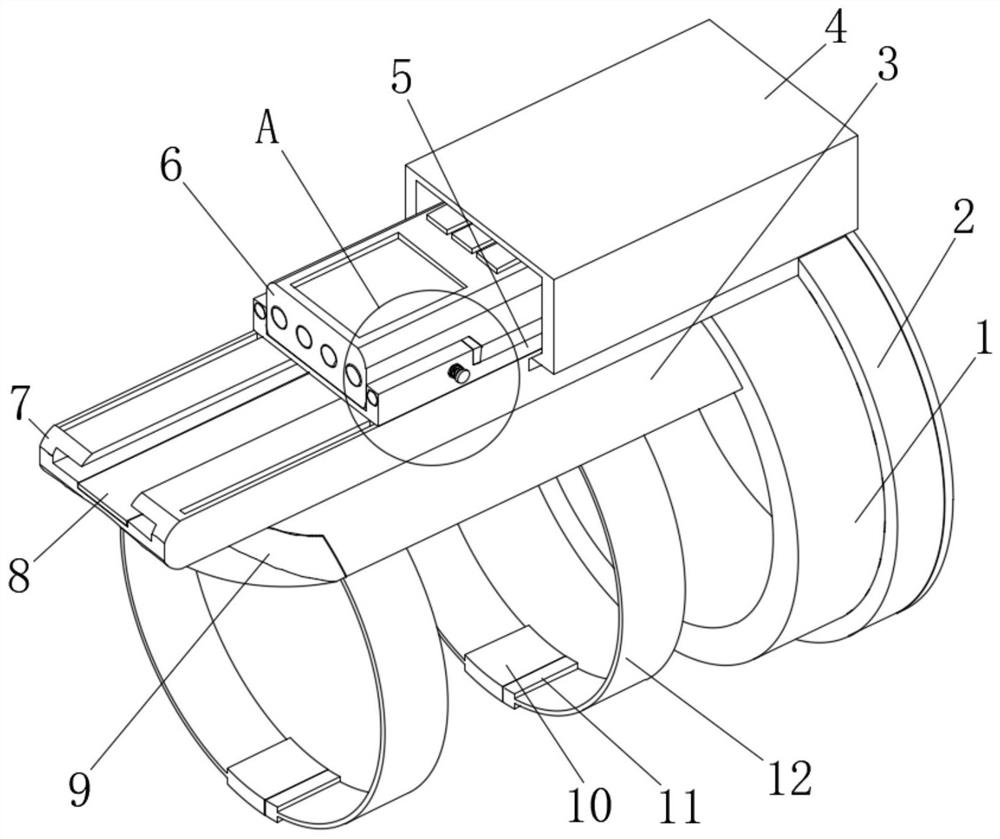
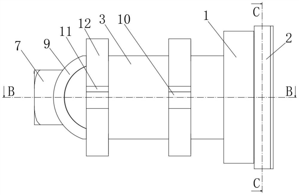
[0027] Embodiment 1: a data collector based on RFID technology, including a fixed ring 1, a support base 3 and a fixed base 7;
[0028] Fixed ring 1: There is an embedded groove on the right end, a spring groove is provided on the side of the upper half of the embedded groove, a spring 21 is fixed on the lower side of the spring groove, and a pressing ball 20 is movably placed in the upper end of the spring groove. The upper end is in contact with the side surface of the lower half of the pressing ball 20 , and a position adjusting ring 2 is rotatably connected in the embedded groove. The inner side of the position adjusting ring 2 is arranged in a circular array with fixed-angle pressing bumps 22 , and the ball 20 is pressed against the ball 20 . The side of the adjusting ring 2 is in contact with the side of the fixed-angle pressing bump 22, and the upper attachment seat 19 is fixed on the side of the upper half of the adjusting ring 2. The adjusting ring 2 can be rotated to ...
Embodiment 2
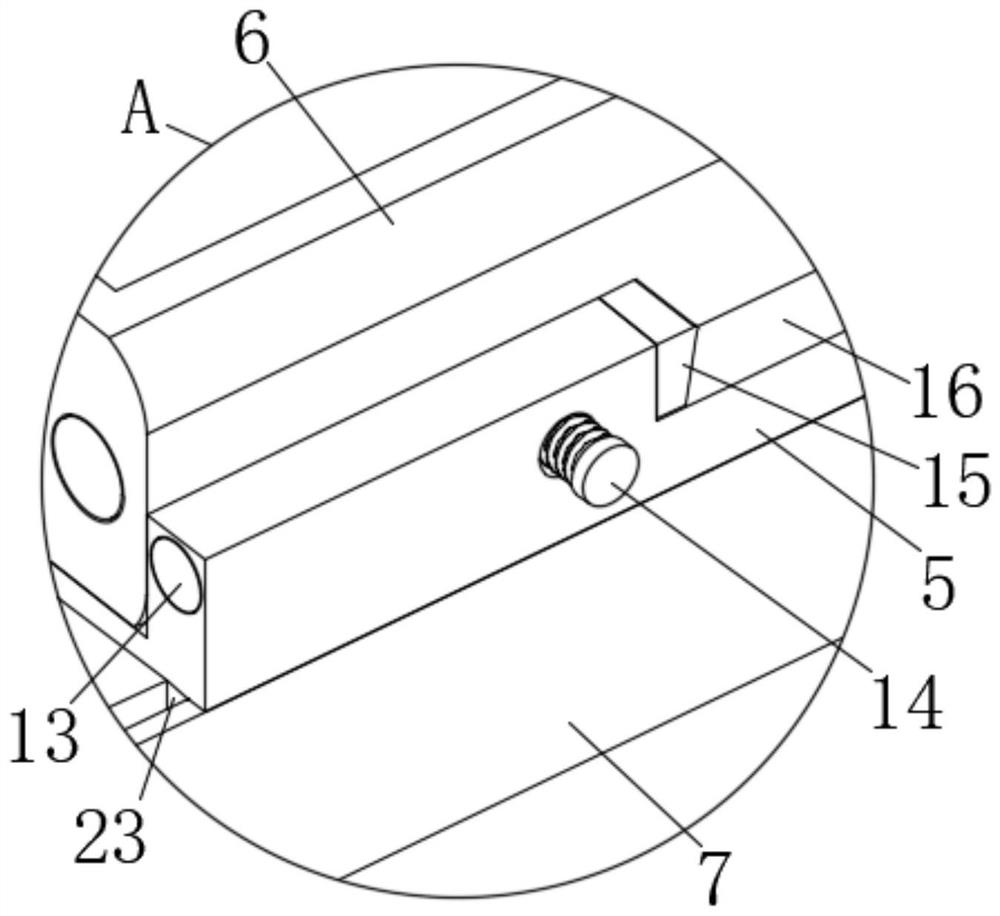
[0032] The difference between this embodiment and the first embodiment is that it also includes side adjusting grooves 16. There are two adjusting side grooves 16 and they are respectively arranged on the upper sides of the front and rear ends of the sliding seat 5. The length dimension of the adjusting side grooves 16 larger than the width of the data collector body 6, the data collector body 6 can be snapped into the adjustment side slot 16 to change the orientation of the data collector body 6 to scan the information codes on different sides of the item, and also include There are four elastic rubber pads 15 for clipping, which are respectively fixed on the left and right sides of the two direction-adjusting side grooves 16, and the data collector body 6 can be clamped and fixed by the elastic rubber pads 15 for clipping, and also includes There is a pressing screw 14. The rear end thread of the pressing screw 14 passes through the front side of the sliding seat 5 and abuts ...
Embodiment 3
[0034] The difference between this embodiment and the second embodiment is:
[0035] In this embodiment, a cloth-covered cushion 9 is also included, and the right end of the cloth-covered cushion 9 is fixed on the left end of the support seat 3 , and the support seat 3 can be prevented from abrading the user's wrist by the cloth-covered cushion 9 . Direct lighting lamps 13, there are two direct lighting lamps 13 and are respectively inserted in the front and rear ends of the left side of the sliding seat 5, the output end of the control device in the data collector body 6 is electrically connected to the input end of the direct lighting lamps 13, The illuminating lamp 13 is convenient for illuminating the information code of the item when the light is poor, and also includes a restriction rod 23. There are two restriction rods 23 and are respectively fixed on the front and rear ends of the lower side of the left end of the sliding seat 5. In the restricting groove, the restric...
PUM
 Abstract
Description
Claims
Application Information