
Distributed cooperative scheduling method and system for multi-micro energy network coupling system

A coupling system and collaborative scheduling technology, applied in forecasting, instrumentation, electrical digital data processing, etc., can solve the problems that the convergence performance of ADMM algorithm is difficult to be effectively guaranteed, and the convergence performance is difficult to be effectively guaranteed, so as to reduce the amount of calculation and ensure The effect of information security

Active Publication Date: 2021-05-28
FUZHOU UNIV
View PDF4 Cites 5 Cited by
  • Summary
  • Abstract
  • Description
  • Claims
  • Application Information

AI Technical Summary

Problems solved by technology

However, the existing distributed optimal scheduling methods generally use the traditional ADMM algorithm to solve, and the convergence performance of the traditional ADMM algorithm is difficult to be effectively guaranteed when solving non-convex problems, that is, when the optimal scheduling model of the multi-micro energy grid coupling system contains When the variable is 0-1, if there is an energy storage device, the scheduling model of the micro-energy network is no longer a convex optimization model, which will make it difficult to effectively guarantee the convergence performance of the ADMM algorithm when solving this problem

Method used


Image

  • Distributed cooperative scheduling method and system for multi-micro energy network coupling system
  • Distributed cooperative scheduling method and system for multi-micro energy network coupling system
  • Distributed cooperative scheduling method and system for multi-micro energy network coupling system

Examples


Embodiment Construction

[0132] The present invention will be further described below in conjunction with the accompanying drawings and embodiments.

[0133] It should be pointed out that the following detailed description is exemplary and is intended to provide further explanation to the present application. Unless defined otherwise, all technical and scientific terms used herein have the same meaning as commonly understood by one of ordinary skill in the art to which this application belongs.

[0134] It should be noted that the terminology used here is only for describing specific implementations, and is not intended to limit the exemplary implementations according to the present application. As used herein, unless the context clearly dictates otherwise, the singular is intended to include the plural, and it should also be understood that when the terms "comprising" and / or "comprising" are used in this specification, they mean There are features, steps, operations, means, components and / or combina...


PUM


Abstract

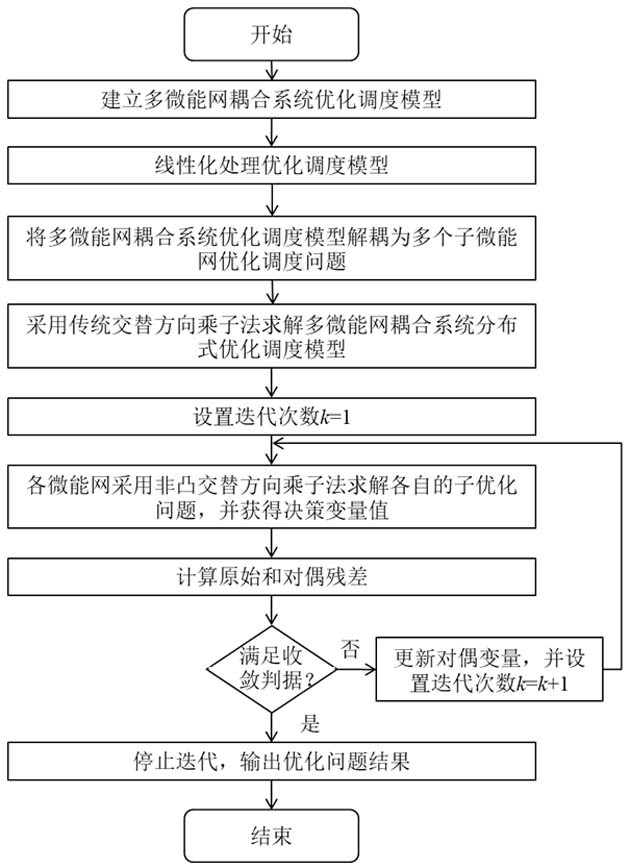
The invention relates to a distributed cooperative scheduling method for a multi-micro-energy-network coupling system, and the method comprises the following steps: S1, building a multi-micro-energy-network coupling system optimization scheduling model, and carrying out the linear processing of the multi-micro-energy-network coupling system optimization scheduling model; s2, decoupling the multi-micro-energy network coupling system optimization scheduling model into a multi-sub-micro-energy network optimization scheduling problem; s3, solving the distributed optimal scheduling model of the multi-micro-energy network coupling system by adopting an alternating direction multiplier method; s4, initializing alternating direction multiplication parameters and setting the number of iterations; s5, enabling each micro-energy network to adopt a non-convex alternating direction multiplier method to solve the respective optimization scheduling problem, and obtaining a decision variable value; calculating original and dual residual errors; and S6, judging whether a convergence condition is met or not, if so, stopping iteration, and outputting an optimal scheduling problem result, namely an optimal scheduling scheme, otherwise, updating the dual variable and the number of iterations, returning to the step S5, and continuing iteration. The method and the system are beneficial to providing an optimal scheduling scheme meeting the load requirement.

Description

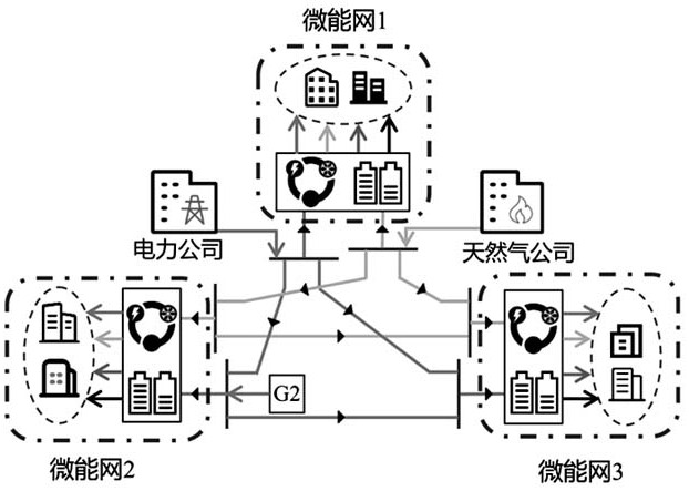
technical field [0001] The invention belongs to the technical field of multi-micro-energy network scheduling, and in particular relates to a distributed collaborative scheduling method and system for a multi-micro-energy network coupling system. Background technique [0002] The development of clean and renewable energy to promote the transformation of the energy structure has become an important means for countries to solve the energy crisis and environmental pollution problems. In this context, micro-energy grids that couple electricity, gas, heat, and cold multi-energy networks have received more and more attention from various countries. With the development of micro-energy networks, multiple micro-energy networks with adjacent geographical locations need to form a multi-micro-energy network coupling system due to interconnection and mutual supply. However, due to information privacy and operational management barriers between micro-energy networks, it is urgent to A di...

Claims


Application Information

Patent Timeline
Patent Type & Authority Applications(China)
IPC IPC(8): G06F30/20G06Q10/04G06Q50/06G06F111/04G06F113/04
CPCG06F30/20G06Q10/04G06Q50/06G06F2113/04G06F2111/04
Inventor 陈飞雄邓宏杰邵振国兰威
Owner FUZHOU UNIV
Learn More