Contaminated soil in-situ solar thermal desorption remediation system

A technology of polluted soil and solar heat, applied in the field of contaminated soil remediation, can solve the problems of poor waste gas collection and high energy consumption, achieve uniform heating, improve energy utilization, and reduce production costs

Active Publication Date: 2022-03-29
STATE GRID HEBEI ELECTRIC POWER CO LTD +1
View PDF7 Cites 0 Cited by
  • Summary
  • Abstract
  • Description
  • Claims
  • Application Information

AI Technical Summary

Problems solved by technology

[0005] The purpose of the present invention is to provide an in-situ solar thermal desorption repair system for polluted soil, which aims to solve the problems of high energy consumption and poor waste gas collection effect in existing in-situ thermal desorption devices for polluted soil

Method used


Image

  • Contaminated soil in-situ solar thermal desorption remediation system
  • Contaminated soil in-situ solar thermal desorption remediation system
  • Contaminated soil in-situ solar thermal desorption remediation system

Examples


Embodiment Construction

[0029] In order to make the technical problems, technical solutions and beneficial effects to be solved by the present invention clearer, the present invention will be further described in detail below in conjunction with the accompanying drawings and embodiments. It should be understood that the specific embodiments described here are only used to explain the present invention, not to limit the present invention.

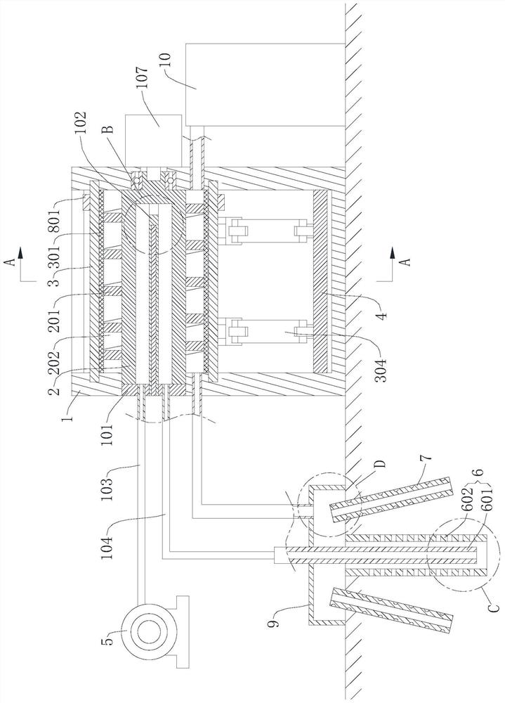
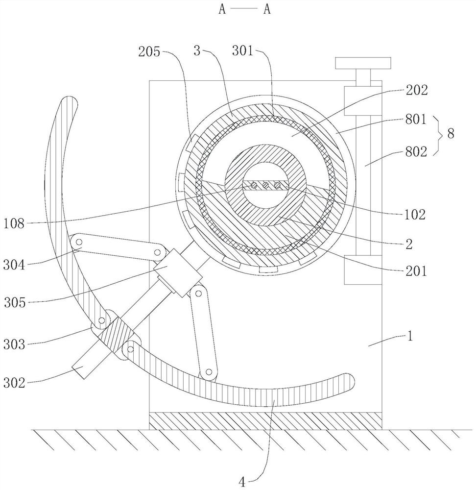
[0030] Please also refer to figure 1 and figure 2 , the in-situ solar thermal desorption restoration system for contaminated soil provided by the present invention will now be described. The in-situ solar thermal desorption restoration system for contaminated soil includes: a support frame 1, a heat collecting tube 2, a heat collecting cover 3, a reflector 4, an air supply part 5, an air injection pipeline 6 and an air extraction pipeline 7; Rotatingly installed on the support frame 1, the outer side of the heat collecting tube 2 is provided with a screw 201; th...


PUM


Abstract

The invention provides an in-situ solar thermal desorption repair system for polluted soil, which belongs to the technical field of polluted soil repair, and includes a support frame, a heat collecting tube, a heat collecting cover, a reflector, an air supply part, an air injection pipe and an air extraction pipe; The heat collecting tube is rotatably installed on the support frame, and the outer side of the heat collecting tube is provided with a spiral piece; the heat collecting cover is installed on the support frame and sleeved on the outside of the heat collecting tube; the waste gas for the passage of exhaust gas is formed between the heat collecting tube and the heat collecting cover channel; the reflector is used to reflect sunlight to the collector tube. The in-situ solar thermal desorption repair system for contaminated soil provided by the present invention uses solar energy to heat the gas, reducing energy consumption; when the waste gas generated by thermal desorption passes through the waste gas channel, it exchanges heat with the gas in the heat collecting tube, and utilizes the waste gas The heat in the heat collecting tube reheats the gas in the heat collecting tube, which not only improves the utilization rate of energy, reduces energy loss, but also improves the heating efficiency of the gas in the heat collecting tube.

Description

technical field [0001] The invention belongs to the technical field of contaminated soil restoration, and more specifically relates to an in-situ solar thermal desorption restoration system for contaminated soil. Background technique [0002] Thermal desorption technology achieves the purpose of separating and removing pollutants from soil particles by heating the polluted soil to above the boiling point of the target pollutant. During the heating process, the target pollutants are evaporated, distilled, boiled, oxidized and pyrolyzed, and the pollutants are transformed from one phase to another, and the fluidity is greatly improved. The in-situ thermal desorption technology separates the target pollutants from the soil under negative pressure conditions without changing the position of the contaminated soil, and finally eliminates them completely or concentrates them in the waste gas treatment facilities. This remediation technology can efficiently remove volatile and semi...

Claims


Application Information

Patent Timeline
Patent Type & Authority Patents(China)
IPC IPC(8): B09C1/06
CPCB09C1/06
Inventor 高冰魏明磊张康崔泽坤杨鹏宫殿楼
Owner STATE GRID HEBEI ELECTRIC POWER CO LTD
Why Eureka
Try Eureka