
Foaming equipment for foamed plastic product production

A foaming equipment and technology of foamed plastics, applied in the field of foamed plastics, can solve problems affecting plastic foaming and coagulation, and achieve the effect of avoiding air entry

Inactive Publication Date: 2021-06-01
刘培芬
View PDF0 Cites 0 Cited by
  • Summary
  • Abstract
  • Description
  • Claims
  • Application Information

AI Technical Summary

Problems solved by technology

[0003] Based on the inventors' findings above, the existing methods mainly have the following deficiencies, such as: when the device is applied in a relatively humid environment, since the discharge port of the foaming device and the inner end of the device are connected in series, the device When heating, the water molecules in the humid air are easy to condense on the inner and outer ends of the device to form water droplets, causing some of the water to condense on the inner end of the device along the penetrating shape of the discharge port, thus affecting the foaming of the plastic foam.

Method used


Image

  • Foaming equipment for foamed plastic product production
  • Foaming equipment for foamed plastic product production
  • Foaming equipment for foamed plastic product production

Examples

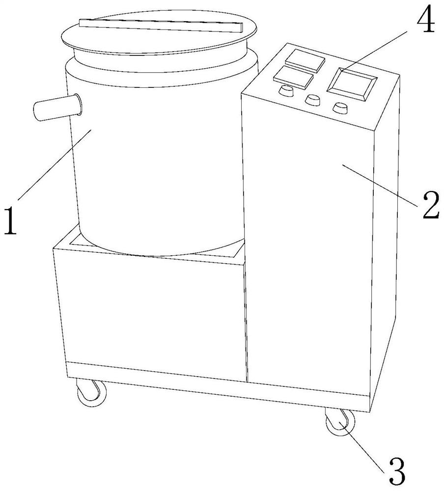

Embodiment 1

[0025] as attached figure 1 to attach Figure 5 Shown:

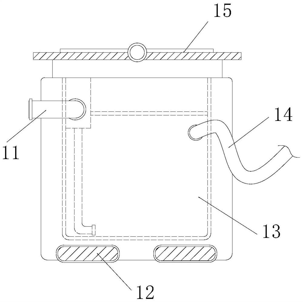
[0026] The present invention provides a foaming equipment for the production of foamed plastic products. Its structure includes a foaming device 1, a body 2, a moving wheel 3, and a control panel 4. The foaming device 1 is installed on the left side of the body 2 by welding On the upper end surface, the upper end surface of the body 2 is inlaid with a control panel 4, the moving wheel 3 is embedded on the lower end surface of the body 2, and the control panel 4 is located on the right side of the foaming device 1; The foaming device 1 comprises an extracting device 11, a heater 12, a placement bucket 13, a foaming agent tube 14, and a hatch cover 15. The extracting device 11 is embedded and installed on the inner left end surface of the foaming device 1, and the heater 12 Symmetrically installed on the left and right sides of the lower end of the placement bucket 13, the placement bucket 13 is inlaid on the inner end s...

Embodiment 2

[0033] as attached Image 6 to attach Figure 7 Shown:

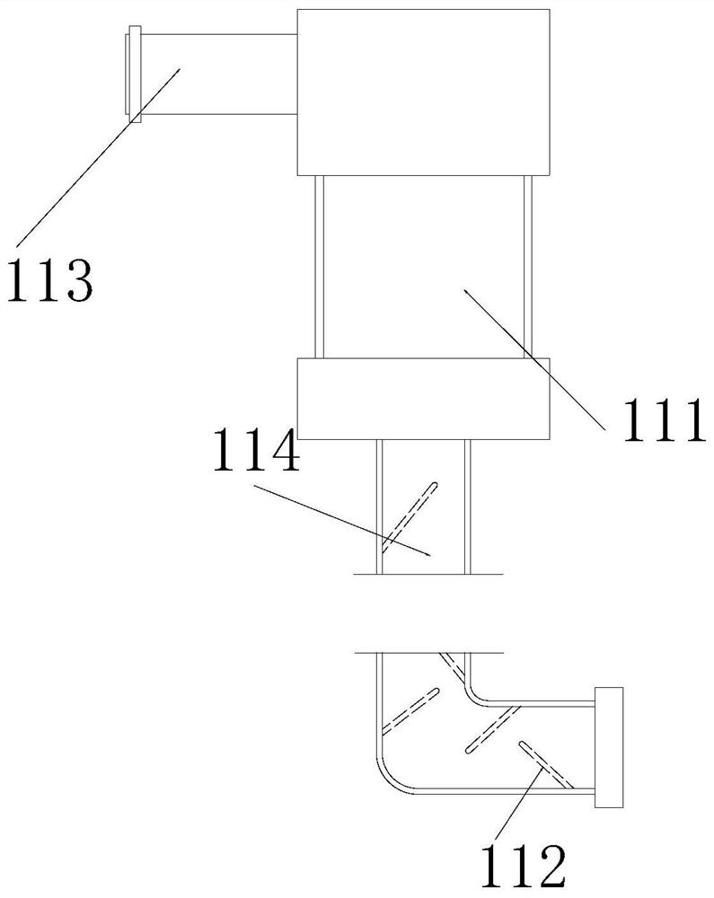
[0034]Wherein, the embedded pipe 113 includes an elastic piece 131, a closing block 132, a push ring 133, and a slide groove 134. The elastic piece 131 is embedded and engaged on the left end surface of the push ring 133, and the closing block 132 is symmetrically installed on the The upper and lower ends of the right side of the push ring 133, the push ring 133 is embedded in the inner end surface of the chute 134, the chute 134 is located on the right side of the elastic sheet 131, the right end surface of the push ring 133 is from the left The diameter gradually decreases to the right to form a slope, which can push up the closing block 132 when it is embedded in the closing block 132 .

[0035] Wherein, the closing block 132 includes a second rubber block 321, a magnetic block 322, a rotating shaft 323, and a swing block 324. The second rubber block 321 is inlaid on the upper end surface of the magnetic block 322, ...


PUM


Abstract

The invention discloses foaming equipment for foamed plastic product production. The foaming equipment structurally comprises a foaming device, a machine body, moving wheels and a control panel, the foaming device is installed on the upper end face of the left side of the machine body through welding, the control panel is installed on the upper end face of the machine body in embedded and clamped manners, and the moving wheels are fixedly embedded in the lower side end face of the machine body; and the control panel is located at the right side of the foaming device. Inflow air and water molecules are intercepted through the angles between covering devices and the fixed end face of an extraction pipe, and when an extractor adsorbs foamed plastic in a containing barrel, adsorption force generated by rapidly-flowing plastic can push the covering devices inwards, so that a swinging plate swings under the inlaying of an inlaying block and an inlaying groove by taking an inlaying shaft as a central fulcrum, the covering devices fixed on the inner end surfaces of the left and right sides of the extraction pipe swing towards the two ends to be close to each other, and the resistance borne when the foamed plastic is adsorbed is reduced.

Description

technical field [0001] The invention belongs to the field of foamed plastics, and more specifically relates to a foaming device for producing foamed plastics products. Background technique [0002] Foaming equipment is a kind of foaming equipment that decomposes and releases gas by heating the chemical foaming agent added to the plastic, so that it can quickly cool the foamed plastic products during the foaming process to make the foam body Cured and set. [0003] Based on the inventors' findings above, the existing methods mainly have the following deficiencies, such as: when the device is applied in a relatively humid environment, since the discharge port of the foaming device and the inner end of the device are connected in series, the device When heating, the water molecules in the humid air are easy to condense on the inner and outer ends of the device to form water droplets, causing some of the water to condense on the inner end of the device along the penetrating sha...

Claims


Application Information

Patent Timeline
IPC IPC(8): B29C44/10B29C44/34
CPCB29C44/10B29C44/35
Inventor 柳锦辉
Owner 刘培芬
Learn More