Injection molding feeding device

A technology for feeding boxes and feeding holes, which is applied in the field of injection molding feeding devices, can solve the problems of plastic raw materials being buckled inside the feeding box, blockage, etc., and achieves the goal of improving carding strength, pressure strength and pressure stability Effect

Inactive Publication Date: 2021-06-01
李敏敏
View PDF6 Cites 0 Cited by
  • Summary
  • Abstract
  • Description
  • Claims
  • Application Information

AI Technical Summary

Problems solved by technology

[0002] In the injection molding operation, the plastic granule raw materials are usually transported to the inside of the injection pipe through the conveying device and the feeding box, and the injection molding screw and the end of the injection pipe inside the injection molding tube can carry out injection molding on the telescopic rod that seals the bottom of the feeding box, but , when the injection molding screw is performing injection molding operations, the telescopic rod that can be sealed at the end of the injection molding screw will seal the bottom of the feeding box. characteristics, so that the raw materials inside the upper material box are extruded and adapted to shrink. When the extrusion shrinks to the appropriate degree, the plastic raw materials will be buckled inside the upper material box, causing blockage. For this reason, we propose An injection molding feeding device

Method used


Image

  • Injection molding feeding device
  • Injection molding feeding device
  • Injection molding feeding device

Examples


Embodiment Construction

[0031]The following will clearly and completely describe the technical solutions in the embodiments of the present invention with reference to the accompanying drawings in the embodiments of the present invention. Obviously, the described embodiments are only some, not all, embodiments of the present invention. Based on the embodiments of the present invention, all other embodiments obtained by persons of ordinary skill in the art without making creative efforts belong to the protection scope of the present invention.

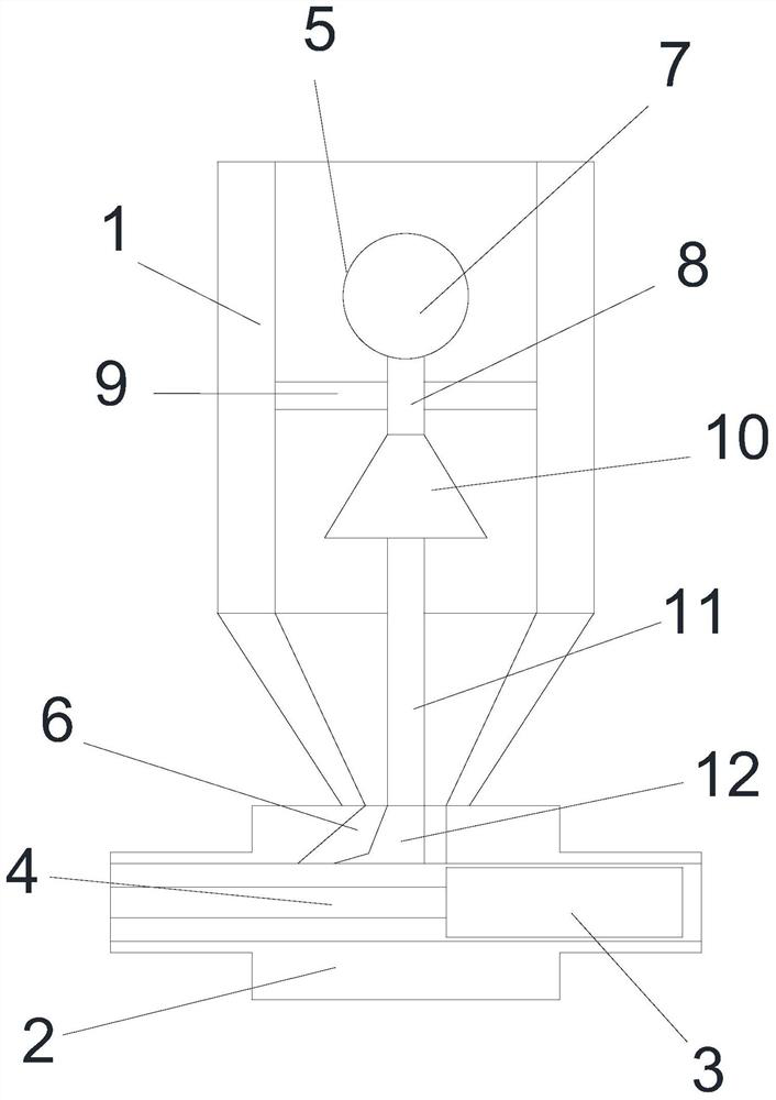
[0032] see Figure 1-Figure 9 , the present invention provides a technical solution: an injection molding feeding device, including a material delivery box 1, the top of the material delivery box 1 is in the shape of a cylindrical box and the bottom is in the shape of a conical box, and the top of the material delivery box 1 is hollowed out , the bottom of the feeding box 1 is fixed with a transmission pipe 2, the transmission pipe 2 is in the shape of a "ten" ...


PUM


Abstract

The invention discloses an injection molding feeding device, and relates to the technical field of injection molding. The injection molding feeding device comprises a material conveying box, wherein a conveying pipe is fixedly mounted at the bottom of the material conveying box, a material conveying hole is formed in the position, corresponding to the bottom of the material conveying box, of the inner side of the conveying pipe, a limiting shaft is arranged at the right end of the inner side of the conveying pipe, the right end of the limiting shaft is fixedly connected with an output shaft of an injection molding device driving device, and an injection molding screw rod is fixedly mounted at the left end of the limiting shaft. According to the injection molding feeding device, along with rotating and rising of an inner adjusting plate, the inner adjusting plate and a plugging adjusting plate can generate pressure on the inner portion of a limiting air block, so that air pressure expands spiral arc blocks and side arc plates on an expanding arc plate and an auxiliary dredging pipe, the storage density of raw materials in the material conveying box is compressed, in this way, after a limiting shaft shrinks, the spiral arc blocks and the side arc plates on the expanding arc plate and the auxiliary dredging pipe shrink, then the storage density in the material conveying box is expanded, and therefore, the effect of carding the raw materials in the material conveying box is achieved.

Description

technical field [0001] The invention relates to the technical field of injection molding, in particular to an injection molding feeding device. Background technique [0002] In the injection molding operation, the plastic granule raw materials are usually transported to the inside of the injection pipe through the conveying device and the feeding box, and the injection molding screw and the end of the injection pipe inside the injection molding tube can carry out injection molding on the telescopic rod that seals the bottom of the feeding box, but , when the injection molding screw is performing injection molding operations, the telescopic rod that can be sealed at the end of the injection molding screw will seal the bottom of the feeding box. characteristics, so that the raw materials inside the upper material box are extruded and adapted to shrink. When the extrusion shrinks to the appropriate degree, the plastic raw materials will be buckled inside the upper material box,...

Claims


Application Information

Patent Timeline
Patent Type & Authority Applications(China)
IPC IPC(8): B29C45/18B29C45/17
CPCB29C45/18B29C45/17
Inventor 李敏敏
Owner 李敏敏
Why Eureka
Try Eureka