
Bubble-removing injection molding device of double-flow-channel structure for preventing gas from flowing in

A dual-flow, gas technology, applied in the field of injection molding, can solve the problems of lack of manual control of injection molding, ensure injection quality, easy to generate air bubbles, etc., achieve good automatic control effect, increase the stability of use, and reduce the effect of air bubbles

Inactive Publication Date: 2021-06-01
林祖承
View PDF6 Cites 0 Cited by
  • Summary
  • Abstract
  • Description
  • Claims
  • Application Information

AI Technical Summary

Problems solved by technology

[0007] The purpose of the present invention is to provide a double channel structure anti-gas inflow defoaming injection molding device, to solve the problem that the currently used injection molding device proposed in the above background technology mainly provides pressure for the injection molded body through the pump body parts and sprays, through the pump Bubbles are likely to be generated during liquid transportation, which is not conducive to ensuring the quality of injection molding. It does not have the function of manual control of injection molding, and cannot freely and flexibly control the injection and delivery of injection molding liquid according to injection molding needs.

Method used


Image

  • Bubble-removing injection molding device of double-flow-channel structure for preventing gas from flowing in
  • Bubble-removing injection molding device of double-flow-channel structure for preventing gas from flowing in
  • Bubble-removing injection molding device of double-flow-channel structure for preventing gas from flowing in

Examples


Embodiment Construction

[0031] The following will clearly and completely describe the technical solutions in the embodiments of the present invention with reference to the accompanying drawings in the embodiments of the present invention. Obviously, the described embodiments are only some, not all, embodiments of the present invention.

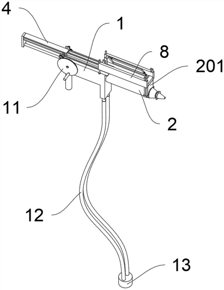
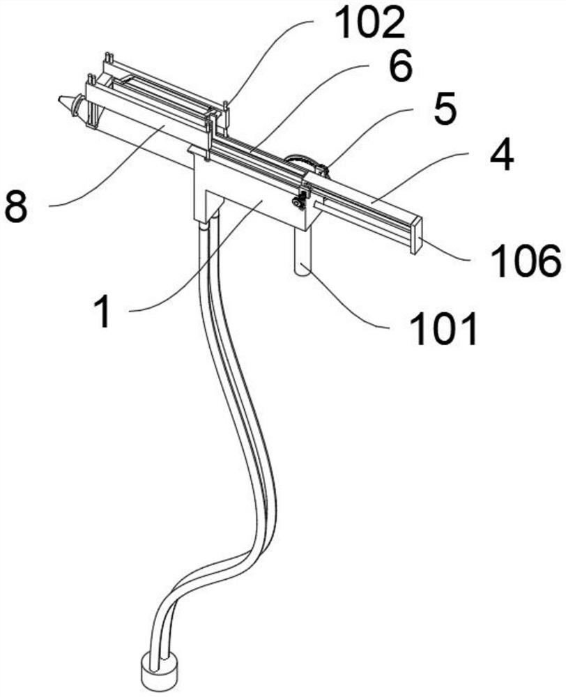
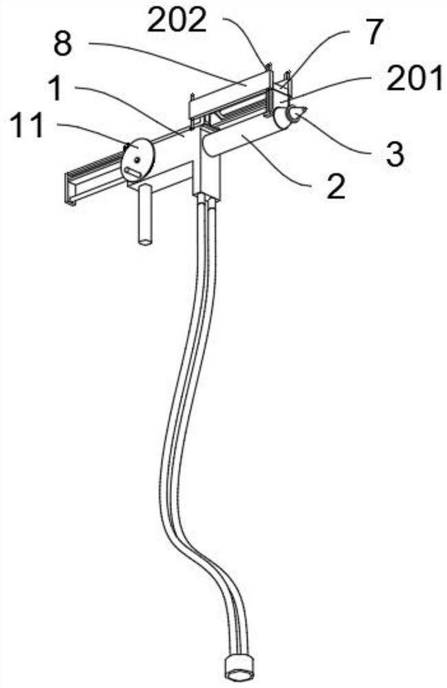
[0032] see Figure 1 to Figure 8, an embodiment provided by the present invention: a defoaming injection molding device with a double-channel structure to prevent gas inflow, including a hand barrel 1; the hand barrel 1 also includes a handle 101, a guide rod A102, a guide bar 103, and a piston plate 104 , guide rod B105, outer plate 106; the bottom rear side of the muff 1 is fixedly provided with a handle 101; A set of guide strips 103; a piston plate 104 is slidably arranged inside the muff 1, and a guide rod B105 is fixedly arranged on the rear end of the piston plate 104, and an outer plate 106 is fixedly arranged on the rear end of the guide rod B105 passing thr...


PUM


Abstract

The invention discloses a bubble-removing injection molding device of a double-flow-channel structure for preventing gas from flowing in, and relates to the technical field of injection molding. The problems that according to an injection molding device used at present, pressure is provided mainly through a pump body part to convey and spray an injection molding body, and bubbles are prone to be generated during conveying by the pump body so that the injection molding quality cannot be guaranteed are solved. The bubble-removing injection molding device of a double-flow-channel structure for preventing gas from flowing in comprises a hand barrel, a conveying barrel is integrally arranged on the front side of the hand barrel, the front end of the conveying barrel is connected with an injection molding opening piece, and vacuum heat preservation layers are arranged on the inner walls of the hand barrel and the conveying barrel. According to the device, by arranging the conveying barrel, a piston plate and a sliding piece, the injection molding device has a manual suction injection molding function convenient to control; a driving wheel disc is rotated to drive a driven shaft to rotate, and the sliding piece can be pushed forwards and backwards through cooperation of a linkage gear and a rack, so that a control effect is good; and pump body conveying is replaced so that gas can be prevented from flowing in, and bubbles can be reduced.

Description

technical field [0001] The invention relates to the technical field of injection molding, in particular to a defoaming injection molding device with a double-channel structure to prevent gas inflow. Background technique [0002] The injection molding device is the main molding equipment for making thermoplastics or thermosetting plastics into various shapes of plastic products with plastic molding molds. It is divided into vertical, horizontal, and all-electric types. The injection molding machine can heat the plastic and apply high pressure to the molten plastic. It is shot out to fill the mold cavity. [0003] After searching, for example, the patent No. CN102380934B discloses an injection device for an injection molding machine, which includes a flange, a molten material supply channel, a feeding cylinder and an injection cylinder connected to the flange, and the feeding cylinder passes through the molten material. The supply channel supplies the molten material to the i...

Claims


Application Information

Patent Timeline
Patent Type & Authority Applications(China)
IPC IPC(8): B29C45/53
CPCB29C45/531
Inventor 林祖承
Owner 林祖承
Learn More