Tow collecting equipment for carbon fiber production

A carbon fiber and equipment technology, applied in the field of wire collection, can solve the problems of large mold width, affecting the beauty of the wire, and clutter.

Pending Publication Date: 2021-06-01
胡亚华
View PDF22 Cites 2 Cited by
  • Summary
  • Abstract
  • Description
  • Claims
  • Application Information

AI Technical Summary

Problems solved by technology

[0006] The invention provides a tow collection device for carbon fiber production, one of the purposes is to have the feature of finely straightening the wrinkled threads, and to solve the problem that the messy threads will become very messy when collected, so that the silk threads will be affected The problem of aesthetics; another purpose is to solve the problem that the width between the molds is too large, which causes the silk thread to deviate from the original position when collecting, so as to achieve the effect of finely collecting the molds

Method used


Image

  • Tow collecting equipment for carbon fiber production
  • Tow collecting equipment for carbon fiber production
  • Tow collecting equipment for carbon fiber production

Examples


Embodiment 1

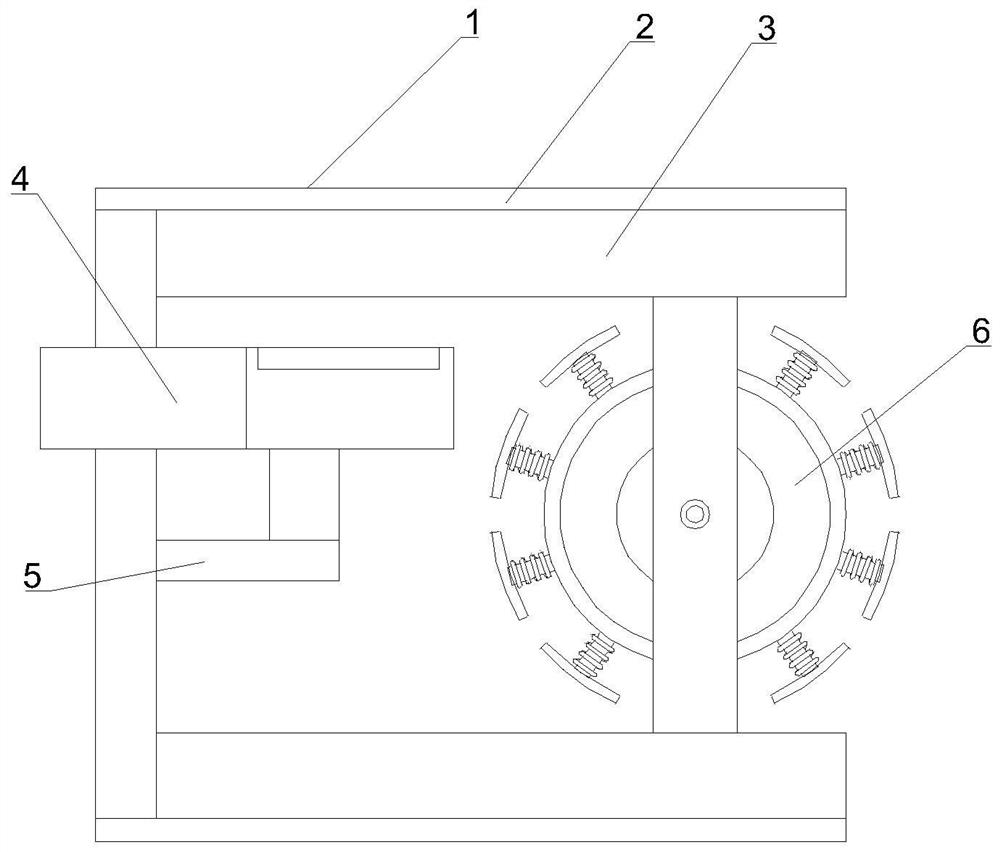
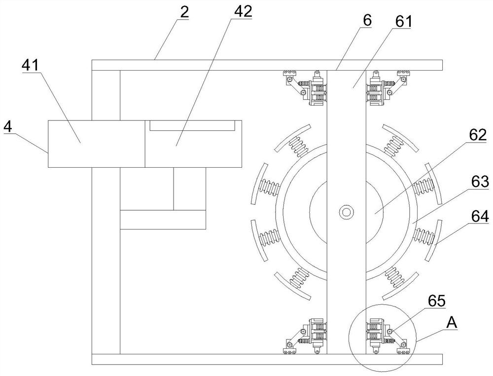
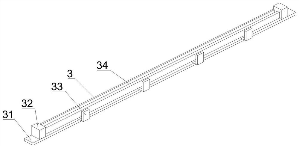
[0056] like Figure 1-10 As shown, the present invention provides a tow collection device for carbon fiber production, including a tow collection device body 1, an outer frame 2, a slide rail groove 3 and a wire groove 4, and the tow collection device body 1 includes an outer frame 2. The outer surface of the outer frame 2 is fixedly connected with a slide rail groove 3, the inside of the outer frame 2 is provided with a wire passing groove 4, the outer surface of the outer frame 2 is fixedly connected with a supporter 5, and the inside of the slide rail groove 3 Active connection has receiving device 6.

[0057] The wire trough 4 includes a heating cylinder 41 , and a cooling cylinder 42 is fixedly connected to the outer surface of the heating cylinder 41 .

[0058] The collecting device 6 includes a pillar 61 , a slider 65 is fixedly connected to the outer surface of the pillar 61 , and the collecting device 6 includes a hub 64 .

[0059] In this embodiment, through the co...

Embodiment 2

[0062] like Figure 1-10 As shown, on the basis of Embodiment 1, the present invention provides a technical solution: preferably, the heating cylinder 41 includes a casing 411, and the inside of the casing 411 is movably connected with an inner sliding column 412, and the outer surface of the inner sliding column 412 A heater 413 is arranged on the top, and one end of the inner sliding column 412 is fixedly connected with a line port 414. The cooling cylinder 42 includes a connecting column 421, and a rotating ring 422 is movably connected to the outer surface of the connecting column 421. The outer surface of the rotating ring 422 An arc connecting rod 423 is fixedly connected to the top, and an outer arc block 424 is fixedly connected to one end of the arc connecting rod 423 , and a cooling hole 425 is arranged on the upper surface of the outer arc block 424 .

[0063] In this embodiment, the thread passes through the thread opening 414, and the heater 413 is used to heat th...

Embodiment 3

[0065] like Figure 1-10 As shown, on the basis of Embodiment 1, the present invention provides a technical solution: preferably, the hub machine 64 includes a second bottom plate 641, a spring post 642 is arranged on the outer surface of the second bottom plate 641, and one end of the spring post 642 Fixedly connected with a receiving groove 643, the collecting groove 643 includes a groove plate 6431, the outer surface of the groove plate 6431 is fixedly connected with a pusher 6432, and the outer surface of the groove plate 6431 is fixedly connected with a fixer 6433, and one end of the fixer 6433 is fixed A U-shaped sleeve 6434 is connected, and a hub block 6435 is fixedly connected to the outer surface of the U-shaped sleeve 6434 .

[0066] In this embodiment, the receiving grooves 643 are evenly distributed on the surface of the wire gathering machine 64, and then the pushing machine 6432 is extended to change the width between the collectors, and the collected wires are ...


PUM


Abstract

The invention discloses tow collecting equipment for carbon fiber production, and relates to the technical field of silk yarn collection. The tow collecting equipment comprises a tow collecting equipment body, an outer frame, a sliding rail groove and a yarn passing groove, the tow collecting equipment body comprises the outer frame, the sliding rail groove is fixedly connected to the outer surface of the outer frame, the yarn passing groove is formed in the outer frame, a bearing device is fixedly connected to the outer surface of the outer frame, a collecting device is movably connected into the sliding rail groove, and the yarn passing groove comprises a heating cylinder. The tow collecting equipment slides through sliding wheels, pulling is conducted through tension springs on the surfaces of second movable rods during sliding, supporting columns are fixed through second buffer springs, buffering can be conducted during moving, the tow collecting equipment has the characteristic that the moving supporting columns are buffered and pulled, the problem that strong jittering is generated due to inertia during movement,so that a mold on the surface of a yarn collecting frame falls off is avoided, and the effect of buffering and pulling the yarn collecting frame is achieved.

Description

technical field [0001] The invention relates to a tow collecting device, relates to the technical field of wire collection, in particular to a tow collecting device used for carbon fiber production. Background technique [0002] Carbon fiber is a special fiber composed of carbon elements. It has the characteristics of high temperature resistance, friction resistance, electrical conductivity, thermal conductivity and corrosion resistance. It is fibrous in shape, soft and can be processed into various fabrics. Preferential orientation, so it has high strength and modulus along the fiber axis direction, and the density of carbon fiber is small, so the specific strength and specific modulus are high. The main use of carbon fiber is to be used as a reinforcing material to compound with resin, metal, ceramics and carbon. Manufacture of advanced composite materials. [0003] There are following problems at prior art: [0004] 1. With the existing tow collection device, the surfac...

Claims


Application Information

Patent Timeline
Patent Type & Authority Applications(China)
IPC IPC(8): B29C70/54B29C71/02D02J13/00
CPCB29C70/54B29C71/02D02J13/00
Inventor 胡亚华
Owner 胡亚华
Why Eureka
Try Eureka