Motion control device of vehicle

A motion control device and vehicle technology, which is applied to the steering control, vehicle components, steering control, etc. installed on the car, can solve the problems of endangering the life safety of the passengers, slipping the steering wheel, and being unable to control the moving direction of the vehicle in a timely and effective manner. Achieve high-efficiency removal and prevent slipping

Active Publication Date: 2021-06-01
如隆智能科技(嘉兴)有限公司
View PDF7 Cites 0 Cited by
  • Summary
  • Abstract
  • Description
  • Claims
  • Application Information

AI Technical Summary

Problems solved by technology

[0003]Maybe due to high air humidity or sweaty palms of the driver in hot weather, the steering wheel will slip in the driver's hand when driving on a complex road surface, causing the The driver cannot control the direction of movement of the vehicle in a timely and effective manner, so that the driver loses control of the vehicle, resulting in a traffic accident that endangers the lives of the occupants

Method used


Image

  • Motion control device of vehicle
  • Motion control device of vehicle
  • Motion control device of vehicle

Examples


Embodiment 1

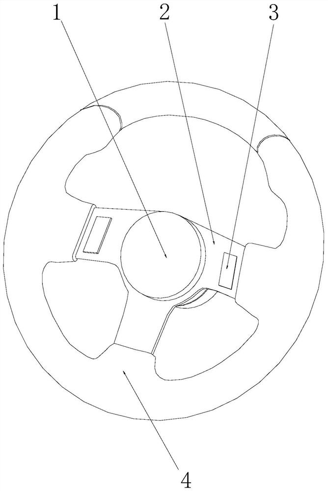
[0026] Example 1: Please refer to Figure 1-Figure 4 , the specific embodiments of the present invention are as follows:

[0027] The invention provides a motion control device for a vehicle, the structure of which includes a rotating shaft 1, a connecting frame 2, a functional contact 3, and a gripper 4, and a connecting frame 2 is embedded and connected between the rotating shaft 1 and the gripping disk 4. The functional contact 3 is installed above the connecting frame 2 .

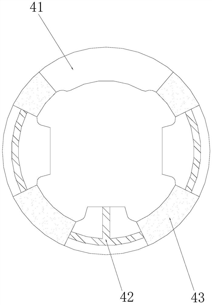
[0028] Described catch 4 is made up of connection block 41, cold pipe 42, anti-skid device 43, and described connection block 41 is provided with four pieces altogether, and described cold pipe 42 is provided with three altogether, and described anti-skid device 43 is provided with four pieces altogether. Four anti-slip devices 43 are installed between the four connecting blocks 41, and the three cold pipes 42 are respectively embedded and connected to the inside of the connecting blocks 41 at the left...

Embodiment 2

[0034] Example 2: Please refer to Figure 5-Figure 8 , the specific embodiments of the present invention are as follows:

[0035] The present invention provides a motion control device for a vehicle. The jacket 344 is composed of a sleeve body 441, a pressure head 442, a groove 443, and a cooling strip 444. The surface of the sleeve body 441 is embedded with a pressure head 442. The groove 443 is provided on the surface of the sleeve body 441. The groove 443 and the sleeve body 441 are an integrated structure. The heat dissipation strip 444 is attached to the inner wall of the sleeve body 441. The groove 443 is a concave arc-shaped structure, and the groove 443 of the concave arc-shaped structure can retain the liquid on the surface of the hand.

[0036] The indenter 442 is composed of a block body 21, a scraper block 22, and a pressing piece 23. The inside of the block body 21 is embedded with a scraper block 22, and the top of the pressing piece 23 is attached to the bottom...


PUM


Abstract

The invention discloses a motion control device of a vehicle. The motion control device structurally comprises a rotating shaft, a connecting frame, a function contact and a grabbing disc, the connecting frame is fixedly connected between the rotating shaft and the grabbing disc in an embedded mode, and the function contact is installed above the connecting frame; by means of the grabbing disc, the temperature of a steering wheel can be reduced, when a driver holds the steering wheel, the temperature of the hands of the driver is reduced, the driver can keep a pleasant mood, and the situation that due to hot weather or emotion tension of the driver, the palm sweats too much, the hands and the steering wheel slip, and a vehicle loses control is prevented. Besides, liquid on the hands of the driver can be scraped off and reserved on the surface of an outer sleeve, the contact face of the hands of the driver and the steering wheel can be rapidly cooled, the liquid on the hands of the driver is efficiently removed, and slipping is prevented.

Description

technical field [0001] The present invention relates to the field of motion control, and more specifically, relates to a motion control device for a vehicle. Background technique [0002] The steering wheel of a car is a very important part of the vehicle's motion control device. It uses the driver's physical strength as the steering energy. All the force transmission parts are mechanical and consist of three parts: the steering control mechanism, the steering gear and the steering transmission mechanism. , Steering wheel From the perspective of lightness of manipulation, stability and safe driving, more advanced techniques are widely used in automobile manufacturing, and variable speed ratio steering gear and high rigidity steering gear are used. The gear ratio and high rigidity are the most advanced steering gear structures produced in the world. direction, but the prior art has the following deficiencies: [0003] It may be due to the high air humidity, or the sweating o...

Claims


Application Information

Patent Timeline
IPC IPC(8): B62D1/06
CPCB62D1/06B62D1/065
Inventor 方莉
Owner 如隆智能科技(嘉兴)有限公司
Why Eureka
Try Eureka