Rim propeller and advancing tool adopting same

A thruster and rim technology, applied in the field of fluid thrusters, can solve the problems of not being able to use vortex energy well, affecting the stability of the thruster, unable to convert the propulsion power, etc. Production and maintenance costs, and the effect of improving propulsion efficiency

Inactive Publication Date: 2021-06-01
武汉波依迈科技有限公司
View PDF5 Cites 0 Cited by
  • Summary
  • Abstract
  • Description
  • Claims
  • Application Information

AI Technical Summary

Problems solved by technology

This kind of rim thruster mainly includes the stator and rotor of the motor, the rotor is cylindrical, the propeller blades are built in the rotor, the magnetic poles in the rotor are evenly distributed on the radial circumference of the propeller, and the stator is directly placed on the outer ring of the propeller , corresponding to the magnetic poles, after power on, the rotor is driven to drive the propeller to rotate. It is not difficult to find out from the structure of this kind of rim thruster that the installation space of the motor stator and rotor is extremely limited, and the power of the motor is directly related to the volume, and In order to reduce water resistance, the conduit is required to be as thin as possible, which further limits the installation space of the motor part, so the power of the propeller is also greatly restricted, which becomes one of the key technical bottlenecks that limit the high power of the rim propulsion system; In the propeller propulsion system, the eddy energy in the propeller wake has not been well utilized and cannot be converted into effective propulsion power. At the same time, a dumping moment is generated, which affects the stability of the propeller

Method used


Image

  • Rim propeller and advancing tool adopting same
  • Rim propeller and advancing tool adopting same
  • Rim propeller and advancing tool adopting same

Examples


Embodiment 1

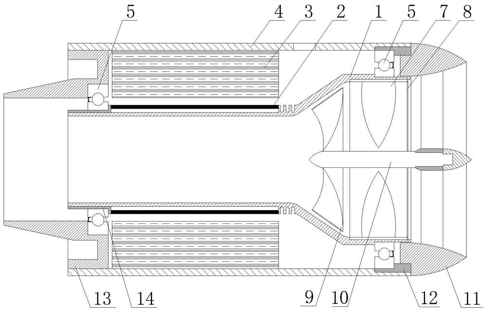
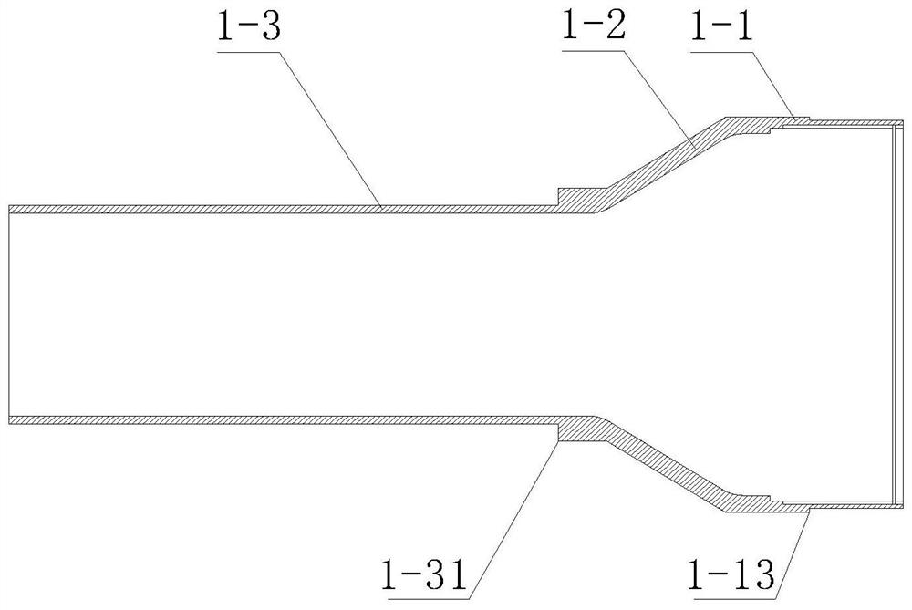
[0034] like Figure 1~3 As shown, a rim propeller includes a rotating shaft 1, a housing 4, a stator 3 and a rotor 2. The rotating shaft 1 is hollow and has a trumpet-like structure, and includes a large end portion 1-1, a small end portion 1- 3 and the transition portion 1-2 between the large end 1-1 and the small end 13-; the large end 1-1 is used to fix the propeller 7, and the small end 1-3 is used to fix The rotor 2 is installed; the rotating shaft 1 is fixedly installed in the housing 4 through the sealed bearing 5, the front end cover 12, the shaft sleeve 14 and the tail end cover 13; the stator 3 provides a radial rotating magnetic field for the rotor 2 to drive The rotor 2 drives the rotating shaft 1 to rotate.

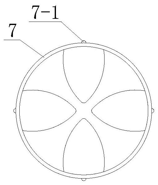
[0035] Further preferably, the propeller 7 is an integral rim type, and is detachably connected to the big end 1-1, and the inner circle of the big end 1-1 is provided with a semicircular keyway 1-11, The propeller 7 is provided with a convex line 7-1 that ...

Embodiment 2

[0038] like Figure 4-8 As shown, a rim propeller includes a rotating shaft 1, a housing 4, a stator 3 and a rotor 2. The rotating shaft 1 is hollow and has a trumpet-like structure, and includes a large end portion 1-1, a small end portion 1- 3 and the transitional portion 1-2 between the large end portion 1-1 and the small end portion 1-3; the large end portion 1-1 is used to fix the propeller 7, and the small end portion 1-3 is used for The rotor is fixedly installed; the rotating shaft 1 is fixedly installed in the housing 4 through the bearing 5, the front end cover 12, the shaft sleeve 14 and the tail end cover 13; the stator 3 provides a radial rotating magnetic field for the rotor 2 to drive the The rotor 2 drives the rotating shaft 1 to rotate.

[0039] Preferably, the propeller 7 is a combined rim type, and is detachably connected to the big end 1-1, and the inner circle of the big end 1-1 is provided with a semicircular keyway 1-11, so The propeller 7 is provided ...

Embodiment 3

[0042] like Figure 9 As shown, a rim propeller includes a rotating shaft 1, a housing 4, a stator 3 and a rotor 2. The rotating shaft 1 is hollow and has a trumpet-like structure, and includes a large end portion 1-1, a small end portion 1- 3 and the transitional portion 1-2 between the large end portion 1-1 and the small end portion 1-3; the large end portion 1-1 is used to fix the propeller 7, and the small end portion 1-3 is used for The rotor is fixedly installed; the rotating shaft 1 is fixedly installed in the housing 4 through the magnetic bearing 5, the front end cover 12, the shaft sleeve 14 and the tail end cover 13; the stator 3 provides a radial rotating magnetic field for the rotor 2 to drive The rotor 2 drives the rotating shaft 1 to rotate.

[0043] Preferably, the propeller 7 is detachably connected to the big end 1-1, the inner circle of the big end 1-1 is provided with a semicircular keyway 1-11, and the propeller 7 is provided with a large The end keyway ...


PUM


Abstract

The invention discloses a rim propeller. The rim propeller comprises a rotating shaft, a shell, a stator and a rotor, the rotating shaft is of a hollow and horn-shaped structure and is movably installed in end covers on the two sides of the shell through a bearing, and the rotating shaft comprises a large end part, a small end part and a gradual change part connecting the large end part and the small end part; a propeller is fixedly mounted on the inner ring of the large end part, and the rotor is fixedly mounted on the outer ring of the small end part; the stator is fixedly mounted on the shell and corresponds to the rotor; and a rectifying piece is arranged at the rear end of a propeller, the rectifying piece is fixed to a flow guide cover through a connecting rod penetrating through a center channel of the propeller, and the flow guide cover is fixedly installed on the shell. The structure characteristics of a pipeline and the the propeller are combined, the Venturi effect is utilized, the contradiction between a high-power driving device and a limited installation space in the rim propeller and the utilization problem of vortex motion energy in the pipeline are well solved, and the propulsion power and the propulsion efficiency of the rim propeller are greatly improved while the small size of the rim propeller is guaranteed,.

Description

technical field [0001] The invention belongs to the field of fluid propellers, in particular to a high-power, high-efficiency, stable-running rim propeller and a traveling tool using the propeller. Background technique [0002] In recent years, with the development of offshore engineering and water entertainment, the performance requirements of propellers have become higher and higher. The disadvantages of traditional shaft-driven propellers have gradually become prominent, and they can no longer better meet the work requirements. For example, the traditional shaft-driven propeller has many components, complex structure, large cabin space, large energy loss, difficulty in controlling vibration and noise, and high construction and maintenance costs. These defects have led people to gradually turn their attention to more advanced shaftless rim propulsion. system. [0003] There are two types of rim-driven propellers: hubless and hubless. At present, in order to reduce resista...

Claims


Application Information

Patent Timeline
Patent Type & Authority Applications(China)
IPC IPC(8): B63H11/02B63H1/28B63H21/17
CPCB63H1/28B63H11/02B63H21/17
Inventor 王前进
Owner 武汉波依迈科技有限公司
Why Eureka
Try Eureka