
An adaptive buffer hydraulic speed limit cutting device, system and method

A cut-off device and self-adaptive technology, applied in the hydraulic field, can solve problems such as severe load shocks and hydraulic system shocks, and achieve the effect of smooth braking performance

Active Publication Date: 2022-07-01
CHONGQING UNIV
View PDF11 Cites 0 Cited by
  • Summary
  • Abstract
  • Description
  • Claims
  • Application Information

AI Technical Summary

Problems solved by technology

[0003] In view of this, the purpose of the present invention is to provide a hydraulic speed-limiting cut-off device, system and method that can make the load softly brake and adaptively buffer when the load descends at an overspeed, aiming at solving the problem of the existing organic-hydraulic speed-limiting cut-off valve. The severe vibration of the load caused by the action and the impact on the hydraulic system

Method used


Image

  • An adaptive buffer hydraulic speed limit cutting device, system and method
  • An adaptive buffer hydraulic speed limit cutting device, system and method

Examples


Embodiment Construction

[0020] The embodiments of the present invention are described below through specific specific examples, and those skilled in the art can easily understand other advantages and effects of the present invention from the contents disclosed in this specification. The present invention can also be implemented or applied through other different specific embodiments, and various details in this specification can also be modified or changed based on different viewpoints and applications without departing from the spirit of the present invention. It should be noted that the drawings provided in the following embodiments are only used to illustrate the basic idea of ​​the present invention in a schematic manner, and the following embodiments and features in the embodiments can be combined with each other without conflict.

[0021] Among them, the accompanying drawings are only used for exemplary description, and represent only schematic diagrams, not physical drawings, and should not be ...


PUM


Abstract

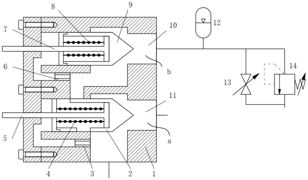
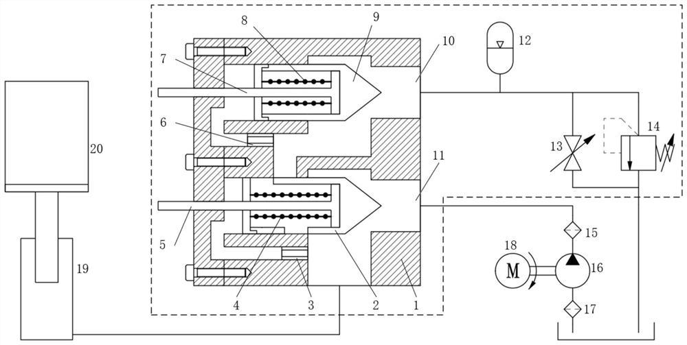
The invention belongs to the technical field of hydraulics, and in particular relates to an adaptive buffering hydraulic speed-limiting cut-off device, system and method, aiming at solving the severe load shock and impact on the hydraulic system caused by the action of the existing machine-hydraulic speed-limiting cut-off valve. question. The hydraulic speed limiting cut-off device includes an accumulator and an adaptive cut-off valve. The adaptive cut-off valve includes a hydraulic valve body. The hydraulic valve body is provided with a main oil circuit chamber and a buffer oil circuit chamber arranged side by side. There is a cut-off valve core and an orifice A. The cut-off valve core is provided with a setting screw A, a return spring A, and two openings that communicate with its inner cavity and respectively lead to the main oil circuit chamber and the buffer oil circuit chamber. A self-adaptive valve core and an orifice B are arranged in the buffer oil circuit chamber, a setting screw B and a return spring B are arranged on the self-adaptive valve core, and the accumulator is connected with the buffer oil circuit chamber. The hydraulic speed limit cut-off device can make the load softly brake when the load falls over speed.

Description

technical field [0001] The invention belongs to the technical field of hydraulics, and in particular relates to an adaptive buffering hydraulic speed limiting cutting device, system and method, which are applied to construction machinery, hydraulic lifting platforms and other occasions. Background technique [0002] Due to its large power-to-weight ratio, hydraulic transmission is easy to achieve stepless speed regulation and precise control, and its motion is stable, and it is widely used in logistics, transportation, marine, construction and other fields. In the actual application process, it is very common to realize vertical load lifting and lowering, such as excavators, cranes, hydraulic elevators, offshore platforms, etc. In these occasions, in order to prevent the load from falling at overspeed due to pipeline rupture, loose joints, etc., a speed-limiting shut-off valve (also known as a pipeline rupture valve) must be installed. That is, when the speed limit cut-off ...

Claims


Application Information

Patent Timeline
Patent Type & Authority Patents(China)
IPC IPC(8): B66B5/04B66B5/16B66C15/00B66F17/00F15B11/08F15B1/02F15B13/02F15B21/041
CPCB66B5/04B66B5/16B66C15/00B66F17/00F15B11/08F15B1/02F15B13/02F15B21/041
Inventor 程敏李林安丁孺琦
Owner CHONGQING UNIV
Learn More