Fabricated beam-column connecting device and connecting method

A beam-column connection and prefabricated technology, which is applied in protective buildings/shelters, building components, and earthquake resistance, can solve problems such as time-consuming, poor structural stability and practicability, and affect the development of prefabricated buildings. Promote and develop obstacles, save time and material costs, enhance the effect of earthquake resistance and practicality

Inactive Publication Date: 2021-06-01
JIANGSU VOCATIONAL INST OF ARCHITECTURAL TECH
View PDF0 Cites 0 Cited by
  • Summary
  • Abstract
  • Description
  • Claims
  • Application Information

AI Technical Summary

Problems solved by technology

[0002] With the continuous development of industry, the industrialization of the construction industry is also the future development trend, but (1) the current prefabricated buildings need to be poured with concrete at the beam-column joints after assembly, and experienced workers are required to carry out assembly work, labor and materials High cost, on-site pouring takes time and slows down the construction period; (2) The current prefabricated beam-column structure is single and cannot be flexibly applied according to the needs of architectural design. It is necessary not to open different molds to meet the design requirements, which increases the cost of molds (3) At the same time, the structure of prefabricated buildings has poor seismic capacity, poor structural stability and practicability, which affects the development of prefabricated buildings

Method used


Image

  • Fabricated beam-column connecting device and connecting method
  • Fabricated beam-column connecting device and connecting method
  • Fabricated beam-column connecting device and connecting method

Examples


Embodiment Construction

[0045] The present invention will be further described below in conjunction with the accompanying drawings in the embodiments of the present invention:

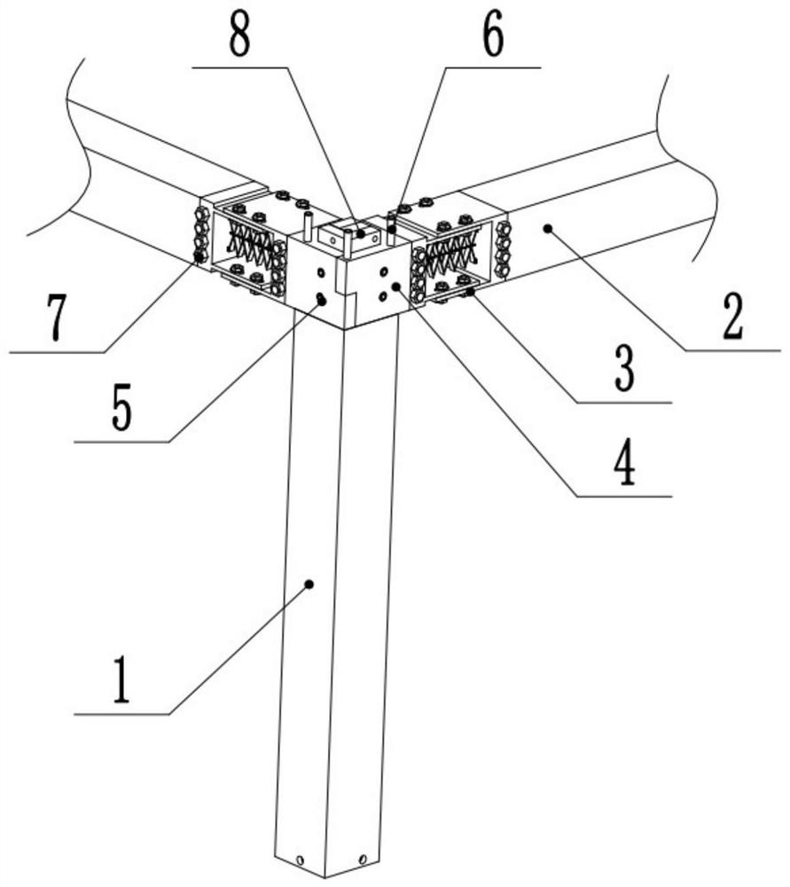
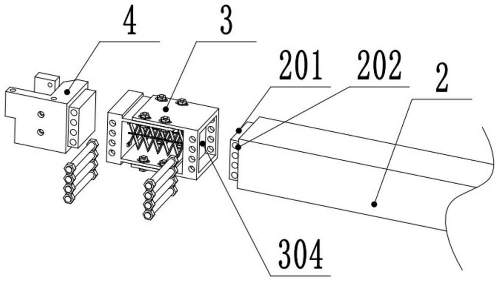
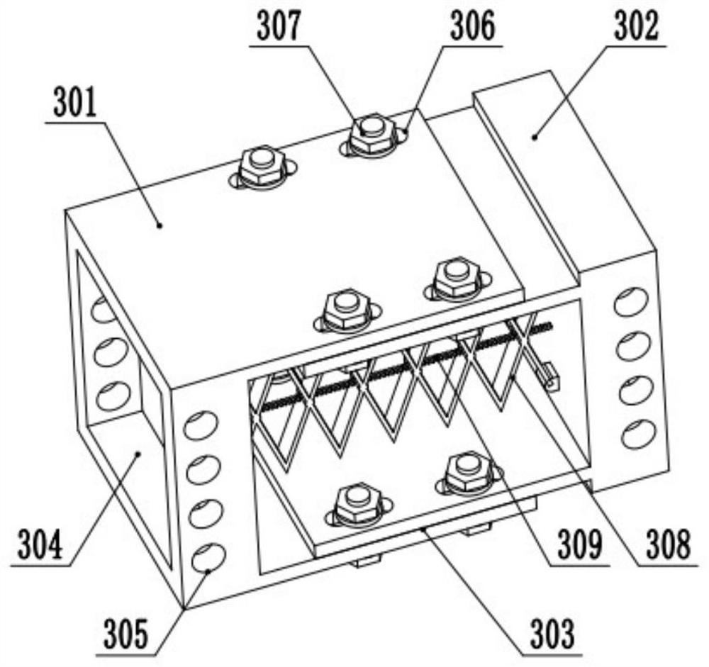
[0046] Such as figure 1 As shown, the prefabricated beam-to-column connection device of the present invention includes a prefabricated column 1, and the top of the prefabricated column 1 is connected with two or three horizontally arranged prefabricated beams 2 through a replaceable joint 4, and the replaceable joint 4 is connected to the prefabricated beam 2 There is a damping device 3 that reduces the lateral vibration between beams and columns. The replaceable joint 4 selects different mortise and tenon structure joints according to the number of prefabricated beams 2 that need to be connected, so that all the prefabricated beams 2 that need to be combined can be connected The replacement joint 4 is spliced ​​to the top of the prefabricated column 1, and a plurality of prefabricated beams 2 are provided with a cylindrical ...


PUM


Abstract

The invention discloses a fabricated beam-column connecting device and a connecting method, and is suitable for the field of buildings. The fabricated beam-column connecting device comprises a prefabricated column, prefabricated beams, damping devices, replaceable joints, replaceable wedge blocks and filling blocks which are combined with one another, wherein the replaceable wedge blocks are mounted at the upper end of the prefabricated column; the damping devices are mounted at two ends of each prefabricated beam; the replaceable joints are mounted on the other sides of the damping devices; and the prefabricated beams are hoisted and spliced at the top end of the prefabricated column. By wedge combination of the wedge blocks and the joints, the fabricated beam-column connecting device is easy to assemble, the labor cost is saved, the fabricated beam-column connecting device can be fastened by bolts after being spliced, concrete does not need to be poured, and the time and material costs are saved. By design of the replaceable joints and the replaceable wedge blocks, different structures can be changed according to different design requirements, a new mold does not need to be arranged, the mold opening cost is saved, and the practicality is improved. The damping devices are mounted at two ends of each prefabricated beam, part of vibration can be eliminated during vibration, the shock resistance and the practicality of a fabricated structure are improved, and the problem that the fabricated structure is hindered by popularization and development is solved.

Description

technical field [0001] The invention relates to a beam-column connection device and a connection method, in particular to a prefabricated beam-column connection device and a connection method suitable for use in the field of construction, and belongs to the field of prefabricated construction. Background technique [0002] With the continuous development of industry, the industrialization of the construction industry is also the future development trend, but (1) the current prefabricated buildings need to be poured with concrete at the beam-column joints after assembly, and experienced workers are required to carry out assembly work, labor and materials High cost, on-site pouring takes time and slows down the construction period; (2) The current prefabricated beam-column structure is single and cannot be flexibly applied according to the needs of architectural design. It is necessary not to open different molds to meet the design requirements, which increases the cost of mold...

Claims


Application Information

Patent Timeline
Patent Type & Authority Applications(China)
IPC IPC(8): E04B1/21E04B1/98E04H9/02
CPCE04B1/21E04B1/215E04B1/98E04H9/021E04H9/025
Inventor 杨宁赵美霞孙道羽单奥博赵明翔尚进赵军
Owner JIANGSU VOCATIONAL INST OF ARCHITECTURAL TECH
Why Eureka
Try Eureka