
Novel electronic detonator ignition element, processing technology and electronic detonator

An electronic detonator and processing technology, applied in weapon accessories, fuzes, offensive equipment, etc., can solve problems such as large PCB board space, damage, and large volume of ignition components, saving PCB area, ensuring resistance consistency, and overall Small size effect

Pending Publication Date: 2021-06-01
东莞市安林电子有限公司
View PDF0 Cites 0 Cited by
  • Summary
  • Abstract
  • Description
  • Claims
  • Application Information

AI Technical Summary

Problems solved by technology

[0003] 1. Existing electronic detonator ignition components are crimped heating wires on the top of the metal bracket, and the crimped part is directly exposed to the air. Due to structural characteristics and some physical and environmental factors, the crimped place in the actual production process Oxidation or rebound will occur after the whole part is pasted in the furnace, which will lead to an increase in the contact resistance between the heating wire and the bridge, and the resistance value of the entire firing element will also be unstable, and it is not easy to identify and avoid, often requiring multiple steps It is very unfavorable for the overall product quality control;
[0004] 2. Existing igniting element brackets protrude directly and are exposed in a large area, which is easily damaged by external forces;
[0005] 3. The existing ignition components are large in size and need to occupy a relatively large PCB board space, which is not conducive to reasonable layout and cost control

Method used


Image

  • Novel electronic detonator ignition element, processing technology and electronic detonator
  • Novel electronic detonator ignition element, processing technology and electronic detonator
  • Novel electronic detonator ignition element, processing technology and electronic detonator

Examples


Embodiment Construction

[0035] In order to make the purpose, technical solutions and advantages of the embodiments of the present invention clearer, a clear and complete description will be made below in conjunction with the technical solutions in the embodiments of the present invention. Obviously, the described embodiments are part of the embodiments of the present invention, and Not all examples. Based on the embodiments of the present invention, all other embodiments obtained by persons of ordinary skill in the art without making creative efforts belong to the protection scope of the present invention.

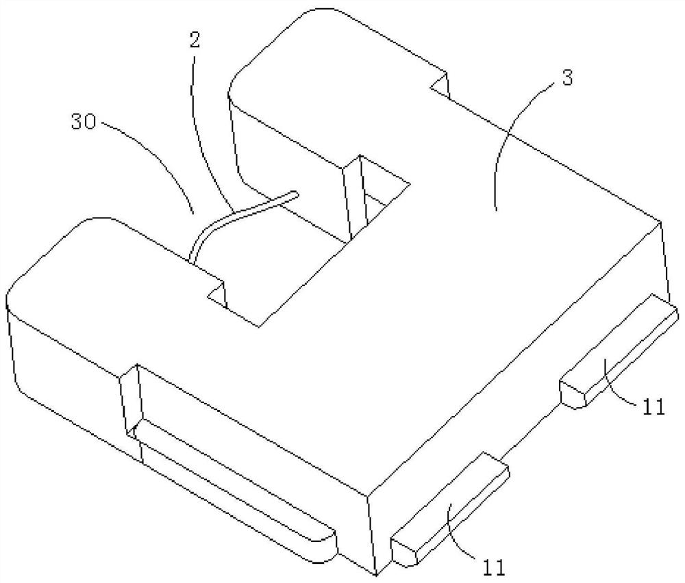
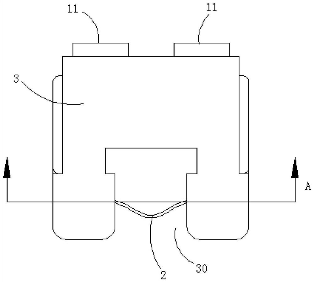
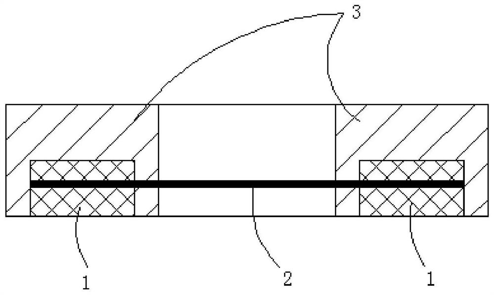
[0036] The novel electronic detonator ignition element of preferred embodiment of the present invention, as figure 1 shown, see also Figure 2-6 , including two side-by-side connecting copper layers 1, the two connecting copper layers 1 are provided with crimping parts 10 for fixing the heating wire 2, and the new electronic detonator ignition element also includes two connecting copper layers a...


PUM


Abstract

The invention relates to a novel electronic detonator ignition element. The novel electronic detonator ignition element comprises two connecting copper layers, wherein crimping parts are arranged on the two connecting copper layers respectively. The novel electronic detonator ignition element further comprises a packaging layer, wherein a packaging gap for partially exposing heating wires is formed in the packaging layer. The two connecting copper layers are both provided with welding parts located outside the packaging layer. The connecting copper layers are packaged and wrapped, the distance between the two sides can be effectively controlled, the distance is the final length of the heating wires, the lengths of the heating wires are consistent, and the resistance consistency of the ignition element is guaranteed. The joints of the connecting copper layers and the heating wires are packaged and wrapped, so that oxidation caused by exposure to air can be effectively avoided, contact resistance increase caused by loosening of the joints due to the influence of environment and time factors is prevented, and the resistance consistency of the ignition element is ensured. Only a small part in the middle of each heating wire is exposed, and the heating wires are protected by the packaging gap and are not prone to being damaged by external force. Compared with an existing ignition element, the ignition element is smaller in overall size and more flexible in design.

Description

technical field [0001] The invention relates to the technical field of electronic detonators, and more specifically relates to a novel electronic detonator ignition element, processing technology and electronic detonator. Background technique [0002] In the electronic detonator industry, the ignition element of the electronic detonator is one of the most critical components of the entire electronic detonator. Whether it can be ignited accurately and effectively directly affects the quality of the entire electronic detonator, and the key to the stability of the ignition is the resistance range of the heating wire. Stable. In the existing process, the heating wire resistance is affected by the contact resistance of the bridge frame and the heating wire crimping under the condition that the diameter and length of the heating wire remain unchanged. Therefore, the contact resistance of the heating wire can ensure the heating wire. resistance to improve the ignition reliability o...

Claims


Application Information

Patent Timeline
Patent Type & Authority Applications(China)
IPC IPC(8): F42C19/12F42C19/08
CPCF42C19/12F42C19/08
Inventor 杨永亮代正华
Owner 东莞市安林电子有限公司
Learn More