
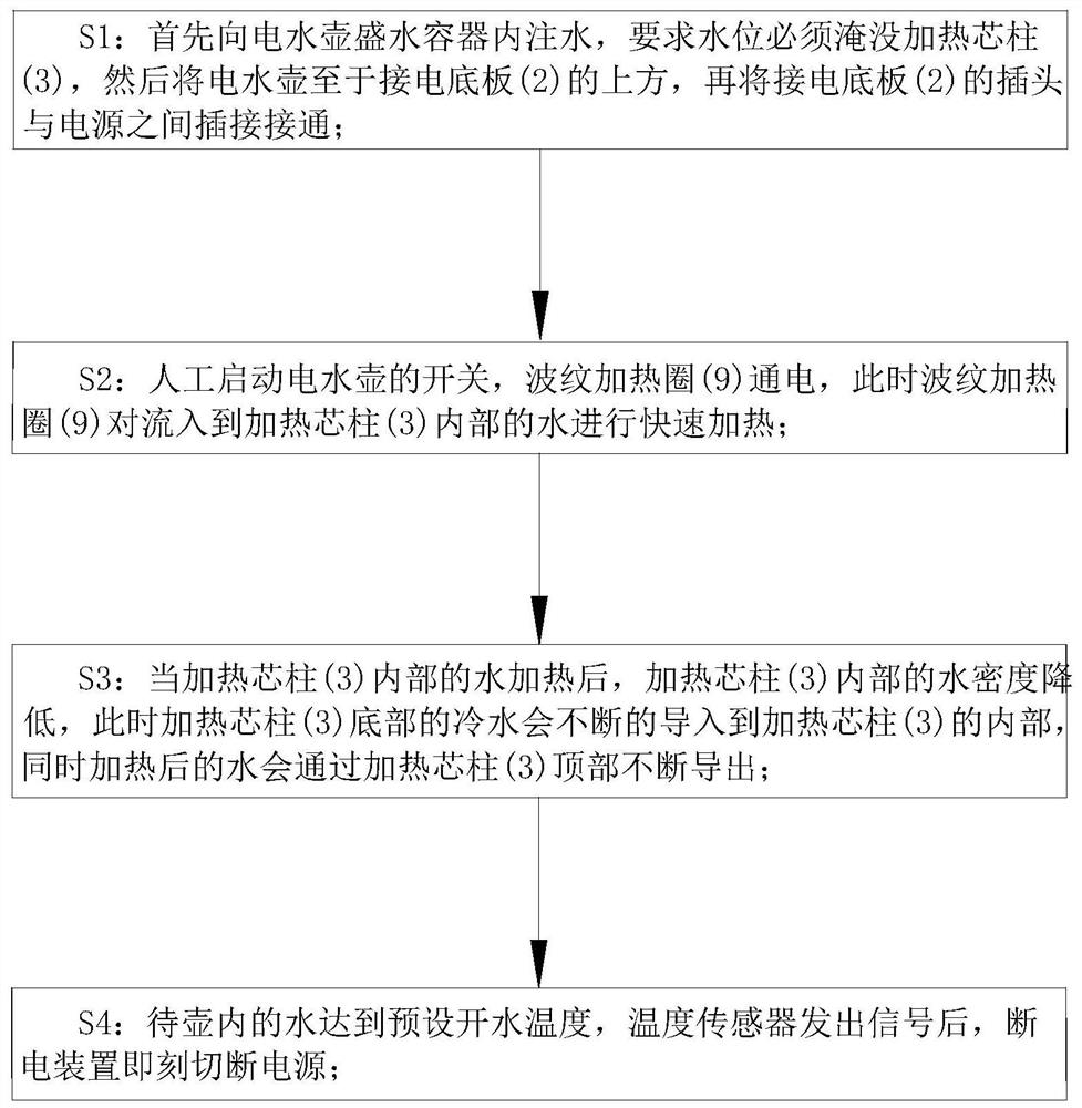
Electric kettle using method

An electric kettle and kettle technology, applied in applications, kitchen utensils, household appliances, etc., can solve the problems of electric kettle vibration, large vibration noise, affecting experience, etc., to facilitate flow, increase the volume of grooves, and improve heating efficiency. Effect

Active Publication Date: 2021-06-04
朱晶晶
View PDF10 Cites 0 Cited by
  • Summary
  • Abstract
  • Description
  • Claims
  • Application Information

AI Technical Summary

Problems solved by technology

[0004] However, in the prior art, the electric kettle realizes the rapid heating of the water inside the electric kettle through the electric heating tube inside, but when the electric kettle is just heated, the inside of the electric kettle will generate relatively large noise, and the water inside the electric kettle will When boiling, there will also be a large vibration noise, which affects the experience of use. The reasons for the noise can be roughly divided into two types. First, when it is just heated, the temperature of the electric heating tube is high, while the temperature of the water The temperature is low, and the water at the position of the electric heating tube is quickly vaporized by high temperature, and small bubbles are formed. When the bubbles are generated, the temperature of the surrounding water is low, which makes the bubbles collapse instantly when they are cold. The formation of a small explosion will cause a large vibration on the inner surface of the electric kettle and cause noise. Second, when the water is boiled, more bubbles will churn, which will also cause the electric kettle and the internal water to vibrate, forming noise, etc. question

Method used


Image

  • Electric kettle using method
  • Electric kettle using method
  • Electric kettle using method

Examples


Embodiment approach

[0042] As an embodiment of the present invention, the surface of the elastic sheet 14 is provided with a fixing hole; the inside of the fixing hole is provided with a push rod 15; the bottom surface of the elastic sheet 14 is fixedly connected with a support block 16; the support block 16 is fixedly connected with a first liquid bag 17 on one side of the corresponding push rod 15; the surface of the support column 8 is fixed with a uniformly arranged second liquid bag 18, and the second liquid bag 18 is connected with the corresponding first liquid bag. The first liquid bag 17 communicates with each other; when working, by setting the first liquid bag 17 and the second liquid bag 18, through the deformation of the elastic sheet 14, the elastic sheet 14 will drive the ejector rod 15 to move, and the ejector rod 15 will correspond to the corresponding first liquid bag. A liquid bag 17 is squeezed, so that the liquid inside the first liquid bag 17 enters into the corresponding sec...


PUM


Abstract

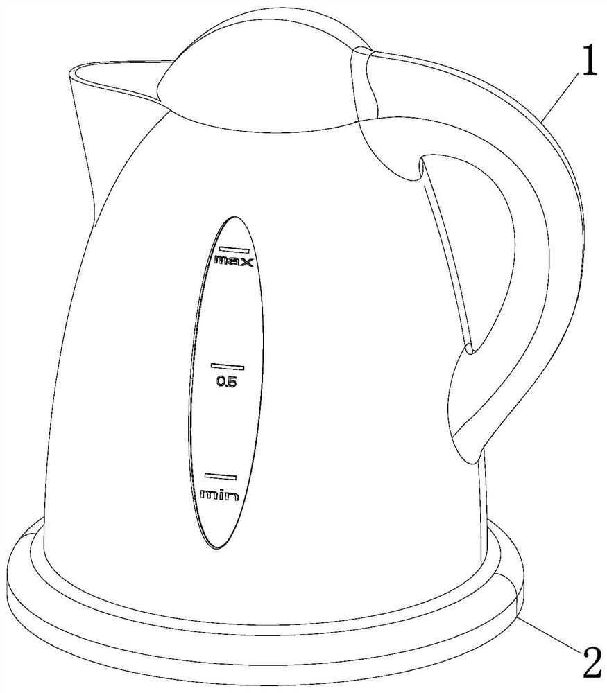
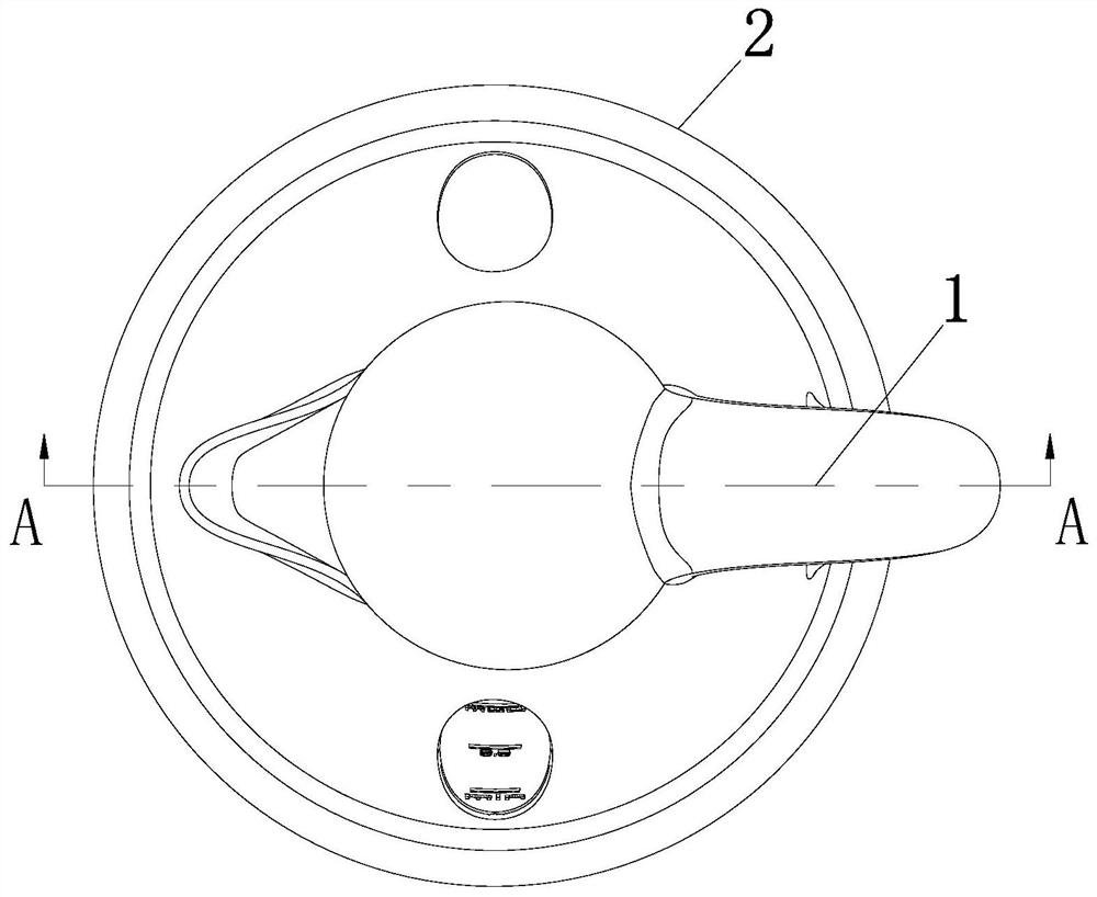
The invention belongs to the technical field of household appliances, and particularly relates to an electric kettle using method, and an electric kettle used in the using method comprises a kettle body and a power connection bottom plate; a power connection bottom plate is arranged at the bottom of the kettle body; a heating core column is fixedly connected to the interior of the kettle body; a heating cavity is formed in the heating core column; a water inlet hole and a water outlet hole which are uniformly distributed are formed in the side surface of the heating core column; the interiors of the water inlet hole and the water outlet hole are fixedly connected with one-way valves; the interior of the heating cavity is fixedly connected with a supporting column; a corrugated heating ring is arranged between the heating core column and the supporting column; and according to the electric kettle, inner layer heating of the electric kettle is effectively achieved, transmission of noise is effectively reduced through enclosure of the heating core column, meanwhile, rapid fusion of bubbles generated in the initial heating stage is facilitated through the corrugated heating ring in the heating core column, breakage of the small bubbles is reduced, noise generation sources are reduced, and the use experience of the electric kettle is improved.

Description

technical field [0001] The invention belongs to the technical field of household appliances, in particular to a method for using an electric kettle. Background technique [0002] As an important heating tool for modern people's drinking water, the electric kettle can provide fast water heating service, so that people can quickly drink a certain amount of hot water. At the same time, the automatic power-off function of the electric kettle can ensure the safety of users. [0003] According to CN101301165B, an electric kettle and its method of boiling water and its use method, through this invention, carcinogenic water or harmful water is eliminated, so that everyone can drink healthy water, and water can be boiled according to the type of water, which will not affect the purity The quality of the water can also make the tap water healthy, and at the same time, the second pot can save electricity and energy consumption when it is kept boiling. [0004] However, in the prior ar...

Claims


Application Information

Patent Timeline
IPC IPC(8): A47J27/21
CPCA47J27/21016A47J36/2461
Inventor 冒薇
Owner 朱晶晶
Learn More