Nuclear spin tomographic radiography equipment with damping plate

A technology of tomography and nuclear spin, applied in the direction of measurement devices, transformer/inductor noise damping, diagnosis, etc., to reduce transmission and damage

Inactive Publication Date: 2003-02-26
SIEMENS AG
View PDF5 Cites 15 Cited by
  • Summary
  • Abstract
  • Description
  • Claims
  • Application Information

AI Technical Summary

Problems solved by technology

[0025] Therefore, the technical problem to be solved by the present invention is to further reduce the noise transmission in the operation of MRT equipment

Method used


Image

  • Nuclear spin tomographic radiography equipment with damping plate
  • Nuclear spin tomographic radiography equipment with damping plate
  • Nuclear spin tomographic radiography equipment with damping plate

Examples


Embodiment approach

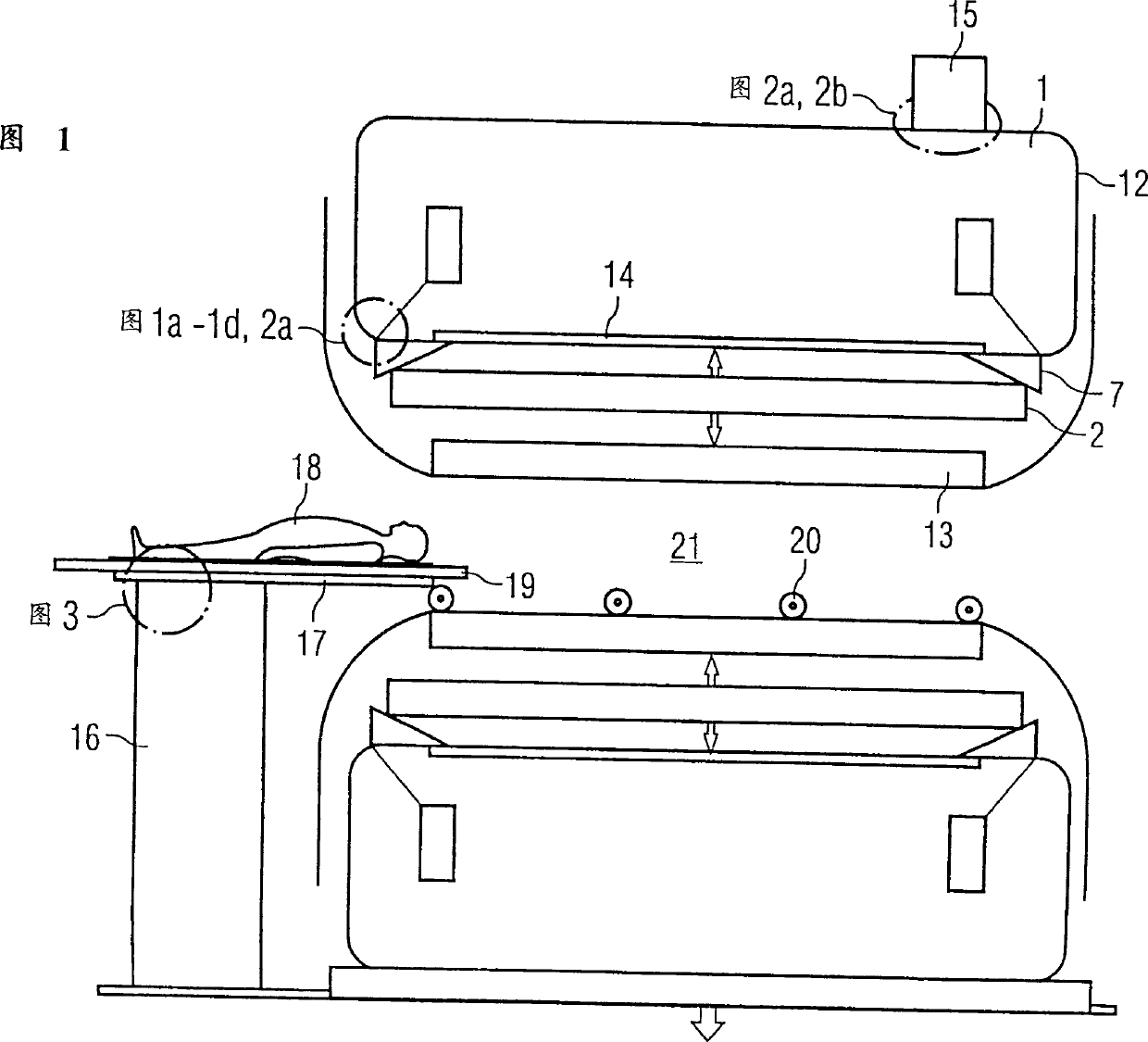
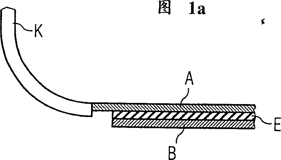
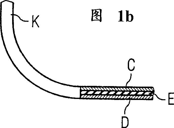
[0055] FIG. 1 a shows a system that employs a double layer structure only on the inner side 14 of the magnetic enclosure 12 that isolates the inner cavity 21 . The inner layer A, like the end face K, is used to form a vacuum inside the magnetic cover 12 to resist the external air pressure. This requires sufficient mechanical rigidity to be able to withstand static negative pressure loads. In the system shown in Figure 1a, only the inner side 14 of the magnetic enclosure 12, which isolates the inner cavity 21, is provided with another shelf B, which need not be vacuum-tight. Its task is to increase the rigidity and damping properties of the inner side 14 . But the actual damping effect comes from the damping layer, that is, the intermediate layer denoted by E between the two layers of plates A and B. This layer is bonded to adjacent metal layers A and B. Since the outer layer B in FIG. 1a has no supporting function, the structure of the magnetic enclosure 12 shown is referre...


PUM


Abstract

The invention relates to a nuclear spin tomographic radiography method (synonym: magnetic resonance imaging method, that is MRT) which is used for patient diagnosis in medicine. The invention especially relates to a nuclear spin tomographic radiography device to reduce vibration of components which constitute a magnetic resonance imaging equipment and reduce propagating paths of noise. This magnetic resonance imaging equipment includes a static magnetic field magnet (1), enclosed by a magnet container (12) for enclosing and bordering an inner space (21) and an inclined magnetic field coil system (2) disposed in this inner space (21). Silencing laminated plate structures (A-E-B, C-E-D) is provided on the inside surface (14) of the magnet container (12) for bordering this inner space (21). Consequently, acoustic vibrations, generated when the inclined magnetic coil system (2) is switched, are absorbed.

Description

technical field [0001] The invention relates generally to nuclear spin tomography (synonym: magnetic resonance tomography, MRT), as it is used in medicine to examine patients. In particular, the invention relates to a nuclear spin tomography apparatus in which vibrations of device components are damped, since such vibrations can have a deleterious effect on the entire system in many respects. Background technique [0002] MRT is based on the physical phenomenon of nuclear spin resonance, which has been used successfully for more than 15 years as an imaging method in the fields of medicine and biophysics. In this examination method, the object is placed in a strong and constant magnetic field, which orients the spins of the otherwise randomly oriented atomic nuclei within the object. The high-frequency waves can then make the "ordered" nuclear spins vibrate in a certain way. This vibration generates the required measurement signal within the MRT, which can be picked up by a...

Claims


Application Information

Patent Timeline
Patent Type & Authority Applications(China)
IPC IPC(8): G01R33/28A61B5/055G01R33/385H01F7/20H01F27/33
CPCG01R33/3854
Inventor 温弗里德·阿茨弗朗兹·博梅尔彼得·迪茨马赛厄斯·韦伯
Owner SIEMENS AG
Why Eureka
Try Eureka