
An auxiliary device for heart transplantation and its application method

A technology of heart transplantation and auxiliary devices, which is applied in the fields of surgery, surgical lighting, medical science, etc., can solve the problems of inconvenient and flexible adjustment of positions, multiple surgical activity spaces, and unfavorable surgical efficiency, so as to facilitate quick access, improve surgical efficiency, The effect of improving surgical efficiency

Active Publication Date: 2022-03-01
XIEHE HOSPITAL ATTACHED TO TONGJI MEDICAL COLLEGE HUAZHONG SCI & TECH UNIV
View PDF10 Cites 0 Cited by
  • Summary
  • Abstract
  • Description
  • Claims
  • Application Information

AI Technical Summary

Problems solved by technology

[0005] The purpose of the present invention is to provide an auxiliary device for heart transplantation and its use method to solve the problem that when the existing surgical auxiliary device is used in heart surgery, it takes up a lot of operation space, and it is not convenient to adjust the position flexibly according to the operation needs. Setting up corresponding auxiliary mechanisms outside the device is not conducive to improving the efficiency of surgery
[0007] In order to realize the above-mentioned auxiliary device for heart transplantation and its use method, the existing surgical auxiliary device occupies a lot of surgical space when used in heart surgery, and it is not convenient to adjust the position flexibly according to the operation needs, and there is no corresponding auxiliary mechanism outside the device , is not conducive to the problem of improving surgical efficiency, the present invention provides the following technical solutions:

Method used


Image

  • An auxiliary device for heart transplantation and its application method
  • An auxiliary device for heart transplantation and its application method
  • An auxiliary device for heart transplantation and its application method

Examples


Embodiment Construction

[0036]The following will clearly and completely describe the technical solutions in the embodiments of the present invention with reference to the accompanying drawings in the embodiments of the present invention. Obviously, the described embodiments are only some of the embodiments of the present invention, not all of them. Based on the embodiments of the present invention, all other embodiments obtained by persons of ordinary skill in the art without creative efforts fall within the protection scope of the present invention.

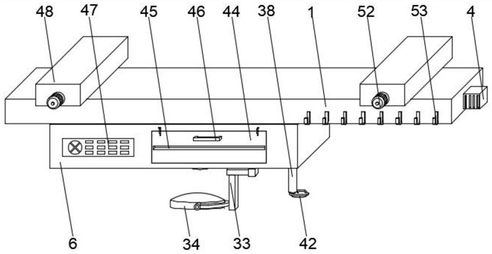
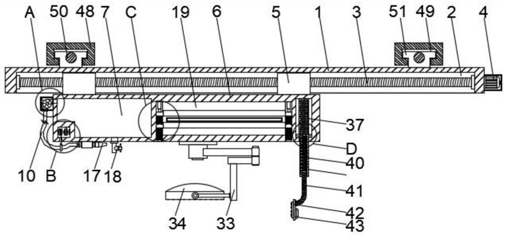
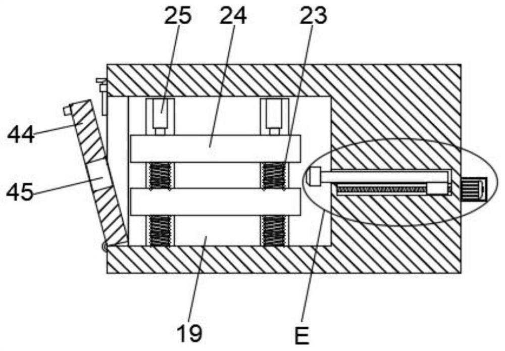
[0037] see Figure 1 to Figure 8 , the present invention provides a technical solution: an auxiliary device for heart transplantation, comprising a top mounting plate 1, the bottom of the top mounting plate 1 is provided with a first sliding groove 2, and the inside of the first sliding groove 2 is slidingly connected with two The first sliding block 5, the bottom of the first sliding block 5 is fixedly installed with a bottom mounting block 6, and one...


PUM


Abstract

The invention discloses an auxiliary device for heart transplantation and a method of use thereof, relating to the technical field of heart transplantation, comprising a top mounting plate, the bottom of the top mounting plate is provided with a first sliding groove, and the inside of the first sliding groove is Two first sliding blocks are slidably connected, the bottom of the first sliding block is fixedly installed with a bottom mounting block, and one side of the inner wall of the bottom mounting block is provided with a blood storage cavity, and the bottom of the bottom mounting block is located at the storage A blood vessel is fixedly installed below the blood chamber, and an outer installation box is fixedly installed on the side of the bottom installation block close to the blood chamber: the beneficial effect of the present invention is that the auxiliary device for heart transplantation is installed by using a top-mounted installation structure, it can be installed on the top of the operating room and above the medical bed when in use, so as to avoid occupying the internal space of the operating room as much as possible, and the device on the top can be more convenient for doctors to use and improve the operation efficiency. efficiency.

Description

technical field [0001] The invention relates to the technical field of heart transplantation, in particular to an auxiliary device for heart transplantation and a method for using the same. Background technique [0002] Heart transplantation is an effective treatment for advanced congestive heart failure. Due to the high difficulty of heart transplantation, a high degree of concentration is required during the operation. At present, multiple assistants usually assist the surgeon. It will make the patient surrounded by more medical staff during the operation, and accidents are prone to occur during the tense operation. [0003] The patent with the application number 201610329040.X discloses a surgical auxiliary device, including a main body of the surgical auxiliary device, an equipment box is arranged on the lower side of the main body of the surgical auxiliary device, a mobile chassis is arranged on the lower side of the equipment box, and a power supply box is arranged ins...

Claims


Application Information

Patent Timeline
Patent Type & Authority Patents(China)
IPC IPC(8): A61B50/22A61B50/20A61B90/30A61B90/35A61M1/00
CPCA61B50/22A61B50/20A61B90/30A61B90/35A61B2217/005
Inventor 董念国尚小珂
Owner XIEHE HOSPITAL ATTACHED TO TONGJI MEDICAL COLLEGE HUAZHONG SCI & TECH UNIV
Learn More