A dry-mixed mortar mixing device

A mixing device and dry-mixed mortar technology, which is applied in the field of mortar mixing, can solve the problems of low mixing efficiency and inability to ensure the mixing quality of materials, and achieve the effects of improving mixing efficiency, facilitating material discharge, and reducing impact force

Active Publication Date: 2021-12-10
深圳市世展建设有限公司
View PDF10 Cites 3 Cited by
  • Summary
  • Abstract
  • Description
  • Claims
  • Application Information

AI Technical Summary

Problems solved by technology

[0005] Aiming at the deficiencies of the prior art, the present invention provides a mortar mixing device, which solves the problem of low mixing efficiency of conventional mixing tanks and the inability to ensure the mixing quality of materials when there are a large amount of materials in the mixing tank

Method used


Image

  • A dry-mixed mortar mixing device
  • A dry-mixed mortar mixing device
  • A dry-mixed mortar mixing device

Examples


Embodiment 1

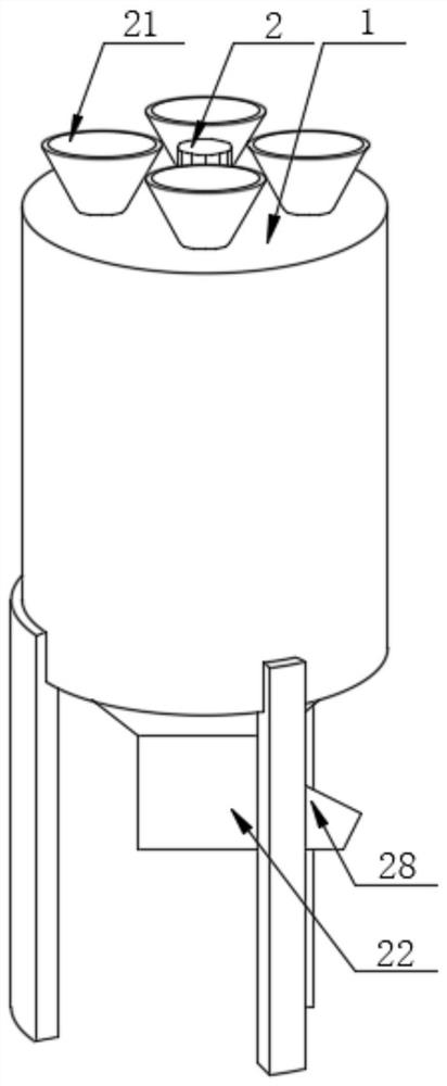
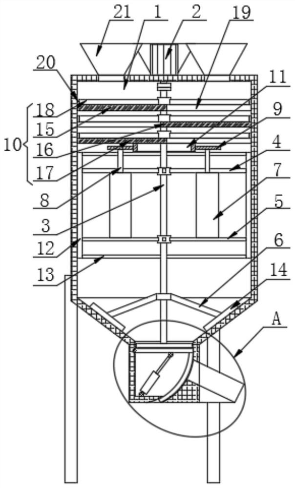
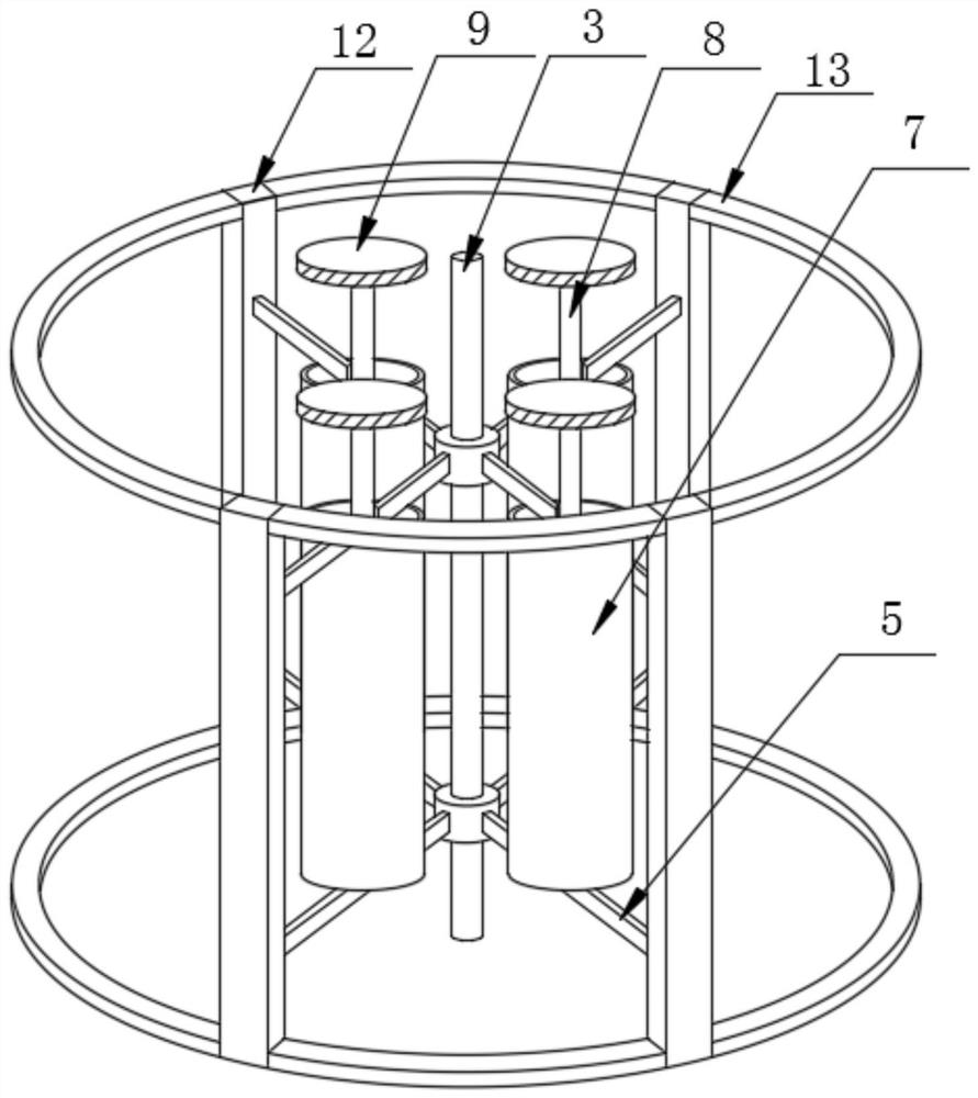
[0031] A dry-mixed mortar stirring device includes a stirring tank 1 and a motor 2 arranged on the stirring tank 1 .

[0032] As a preferred solution, the motor 2 is fixedly installed in the middle of the top of the stirring tank 1, the bottom end of the output shaft of the motor 2 runs through the stirring tank 1 and is fixedly connected with the stirring rod 3 through a coupling, and the outer surface of the stirring rod 3 is sequentially arranged from top to bottom The first stirring support 4, the second stirring support 5 and the third stirring support 6 are sleeved and fixedly connected. A screw feeding rod 8 is connected to the inside of the conveying cylinder 7 through bearing rotation, the top of the conveying cylinder 7 is fixedly connected to the bottom of the first stirring support 4 support plates, and the top of the spiral feeding rod 8 penetrates the first stirring support 4 and is fixed Connected with a gear 9, the inner wall of the stirring tank 1 is fixedly c...

Embodiment 2

[0034] This embodiment is an improvement of the previous embodiment. A mortar stirring device includes a stirring tank 1 and a motor 2 arranged on the stirring tank 1 .

[0035] As a preferred solution, the motor 2 is fixedly installed in the middle of the top of the stirring tank 1, the bottom end of the output shaft of the motor 2 runs through the stirring tank 1 and is fixedly connected with the stirring rod 3 through a coupling, and the outer surface of the stirring rod 3 is sequentially arranged from top to bottom The first stirring support 4, the second stirring support 5 and the third stirring support 6 are sleeved and fixedly connected. A screw feeding rod 8 is connected to the inside of the conveying cylinder 7 through bearing rotation, the top of the conveying cylinder 7 is fixedly connected to the bottom of the first stirring support 4 support plates, and the top of the spiral feeding rod 8 penetrates the first stirring support 4 and is fixed Connected with a gear 9...


PUM


Abstract

The invention discloses a dry-mixed mortar stirring device, which comprises a stirring tank and a motor arranged on the stirring tank, the motor is fixedly installed in the middle of the top of the stirring tank, and the bottom end of the output shaft of the motor runs through the stirring tank and is fixedly connected by a coupling There is a stirring rod, the outer surface of the stirring rod is sequentially set and fixedly connected with the first stirring support, the second stirring support and the third stirring support from top to bottom, and the top of the support plate of the second stirring support is fixedly connected with a conveying cylinder. The invention relates to the technical field of mortar mixing. The mortar mixing device, through the rotation of the screw feeding rod, conveys the material at the bottom of the mixing tank upwards, thereby ensuring the uniform mixing of the materials, which can not only increase the mixing speed, but also improve the mixing quality and greatly improve the mixing efficiency. The setting of the board and the cleaning frame can not only reduce the impact force of falling materials, but also perform a preliminary mixing of various materials, thereby improving the mixing efficiency of dry-mixed mortar.

Description

technical field [0001] The invention relates to the technical field of mortar mixing, in particular to a dry-mixed mortar mixing device. Background technique [0002] Dry-mixed mortar is usually called hydraulic cement mixed mortar, which refers to the physical mixing of aggregates (such as quartz sand), inorganic cementitious materials (such as cement) and additives (such as polymers) that have been dried and screened in a certain proportion. It is a granular or powdery material that is transported to the construction site in bags or in bulk and can be used directly after mixing with water. It is also called mortar dry powder, dry mix, dry mix powder, and some construction adhesives. Also falls into this category. Dry powder mortar plays the role of bonding, padding, protection and decoration in thin layers in the construction industry, and is widely used in construction and decoration engineering. [0003] In the manufacturing process of dry-mixed mortar, it is necessary...

Claims


Application Information

Patent Timeline
Patent Type & Authority Patents(China)
IPC IPC(8): B28C5/16B28C5/08B28C7/16
CPCB28C5/16B28C5/0831B28C5/0806B28C7/16
Inventor 吕和平彭碧奕张才访卢睿臻吴丽妹曾倩苏达池楚星
Owner 深圳市世展建设有限公司
Why Eureka
Try Eureka