
Rail transit power transmission rail insulation support

A rail transit and insulating support technology, applied in the field of rail transit, can solve the problems of inconvenient assembly and disassembly of insulating supports, and achieve the effects of convenient assembly and disassembly, convenient manual operation, and maintenance of stability

Inactive Publication Date: 2021-06-04
唐剑军
View PDF0 Cites 0 Cited by
  • Summary
  • Abstract
  • Description
  • Claims
  • Application Information

AI Technical Summary

Problems solved by technology

[0003] The purpose of the present invention is to solve the shortcomings of the inconvenient assembly and disassembly of the insulating support of the power transmission track existing in the prior art, and the rail transit power transmission track insulating support proposed

Method used


Image

  • Rail transit power transmission rail insulation support
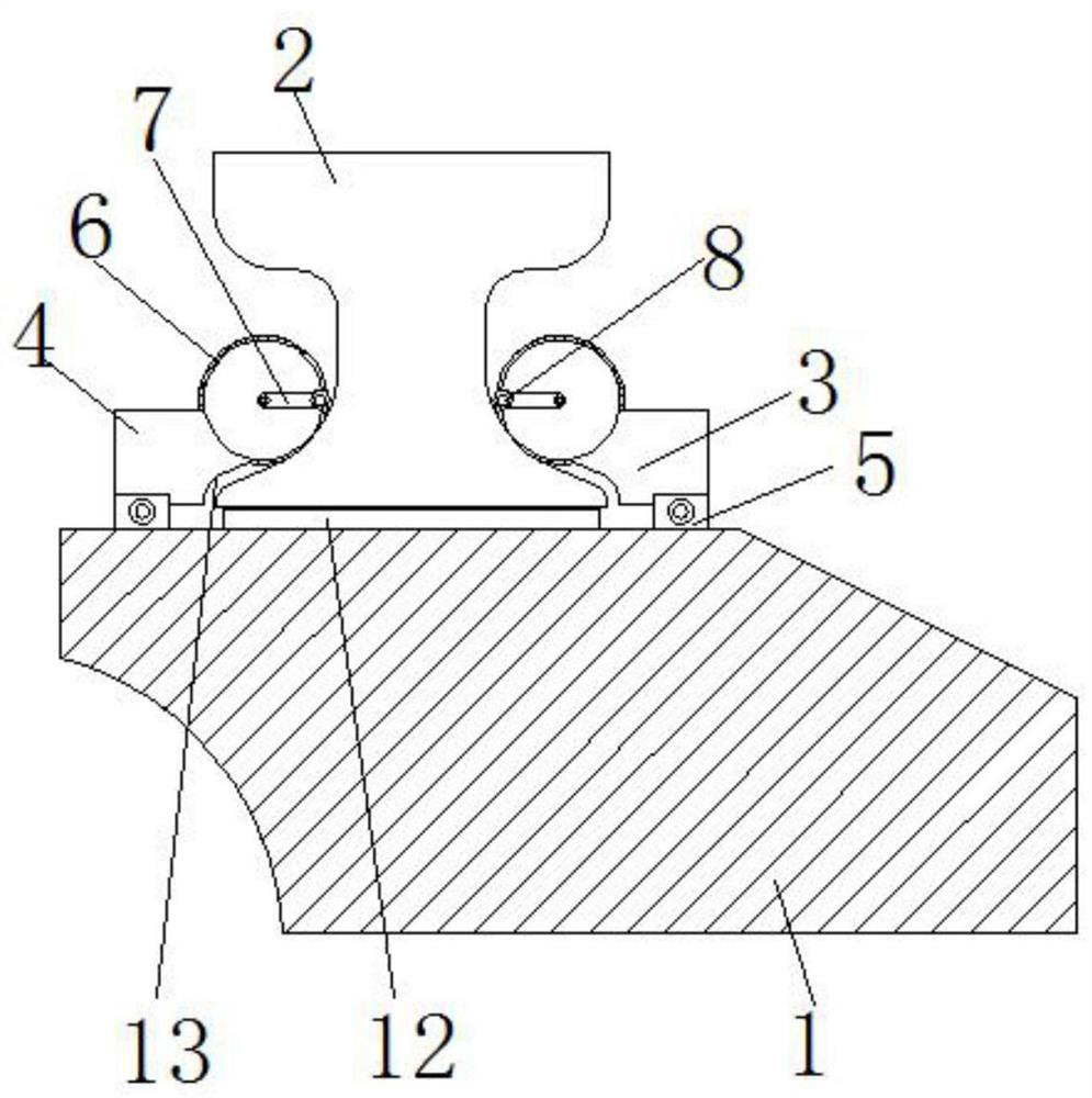
  • Rail transit power transmission rail insulation support
  • Rail transit power transmission rail insulation support

Examples


Embodiment 1

[0019] In Embodiment 1, the limit ball 8 can be replaced by a rotating roller, and the roller surface of the rotating roller can also be pressed against the side of the power transmission track 2 , and the rotating rollers on both sides can also form a clamping shape for the power transmission track 2 .

Embodiment 2

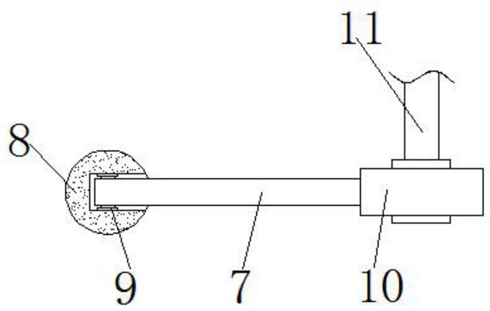
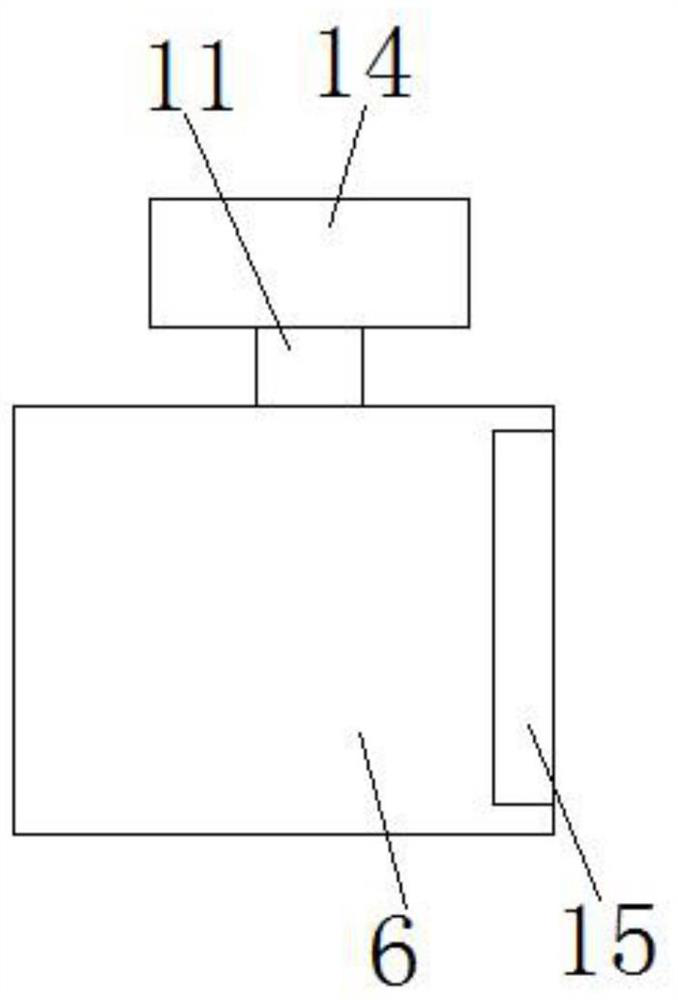
[0020] In the second embodiment, the motor 14 drives the movable arm 7 to rotate automatically, which can also be replaced by manual rotation. The purpose of rotating the movable arm 7 is to control the limit ball 8 at the end to slide to different positions.

Embodiment 3

[0021] In the third embodiment, the movable arm 7 is installed on the connecting seat 10 through the spring shaft, here, the drive shaft 11 becomes a manual adjustment handle, and the adjustment handle controls the rotation and deviation of the movable arm 7, while the spring shaft can ensure its reset.

[0022] Specific working process: both the first clamping block 3 and the second clamping block 4 can be rotated. When the power transmission track 2 needs to be installed or removed, it is only necessary to turn the clamping blocks on both sides outward. When the transmission track 2 is clamped by the clamping blocks on both sides, the clamping gap will be different, that is, the distance between the clamping block and the transmission track 2 is different, which will affect the tightness of the clamping. For this reason, Design the limit ball 8 again, the position of the limit ball 8 is adjustable, the limit block 8 can slide along the outer wall contour of the power transmis...


PUM


Abstract

The invention relates to the technical field of rail transit, in particular to a rail transit power transmission rail insulation support which comprises a supporting base, a power transmission rail is arranged at the top of the supporting base, and a first clamping block and a second clamping block are arranged on the supporting base and located on the two sides of the power transmission rail respectively. Shells are arranged on the upper half portions of the side faces, facing the power transmission rail, of the first clamping block and the second clamping block correspondingly, rotatable movable arms are arranged in the centers of the shells, limiting balls are arranged at the ends, away from the axis, of the movable arms, and the spherical surfaces of the limiting balls abut against the outer wall of the power transmission rail. The problem that an insulation support of the power transmission rail is inconvenient to assemble and disassemble is solved, the movable clamping block design of the insulation support can maintain the stability of the power transmission rail, the adjustable fiber ball design is matched, the position of the power transmission rail is further restrained, it is guaranteed that the position of the power transmission rail is fixed, meanwhile, the design is convenient to assemble and disassemble, convenience is provided for manual operation, and the using effect is good.

Description

technical field [0001] The invention relates to the technical field of rail transit, in particular to an insulating support for rail transit power transmission tracks. Background technique [0002] With the diversified development of train and railway technology, rail transit presents more and more types, not only in long-distance land transportation, but also widely used in medium and short-distance urban rail transit. In urban rail transit system , one side of the track of electric traction vehicles is equipped with a contact rail to transmit power to the vehicle. The contact rail is an important part of the subway power supply system. In the actual installation process of the contact rail, a support system is required. The support system of the transmission track is often equipped with insulating brackets. . The existing insulating support for the power transmission track of rail transit is inconvenient to install and disassemble the power transmission track. Contents ...

Claims


Application Information

Patent Timeline
IPC IPC(8): B60M1/30B60M5/00
CPCB60M1/307B60M5/00
Inventor 唐剑军
Owner 唐剑军
Learn More