Steel pipe discharging roller assembly line

An assembly line and roller technology, applied in the direction of conveyors, rollers, conveyor objects, etc., can solve the problems of steel impact rebound, steel pipe position inclination, difficulty in matching the horizontal relative position of grooves, etc., and achieve the effect of preventing rapid rolling impact.

Inactive Publication Date: 2021-06-04
何超伟
View PDF0 Cites 0 Cited by
  • Summary
  • Abstract
  • Description
  • Claims
  • Application Information

AI Technical Summary

Problems solved by technology

[0006] In order to solve the above-mentioned technology, when the steel pipe is in the process of feeding the drum, it is easy to quickly impact downward through the inclination of the slope and the power of the drum, so that the steel pipe that has been blanked at the front end is impacted and rebounded, causing the position of the steel pipe to tilt. When entering a step process, it is difficult to match the relative position of the groove level

Method used


Image

  • Steel pipe discharging roller assembly line
  • Steel pipe discharging roller assembly line
  • Steel pipe discharging roller assembly line

Examples


Embodiment 1

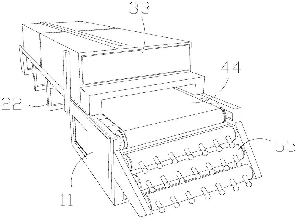
[0032] Append figure 1 Adherent Figure 6 Down:

[0033] The present invention provides a steel pipe lowering roller flow wire, which includes a control box 11, a support frame 22, a treatment tank 33, a roller strip 44, a dispensing cartridge 55, and the roller belt 44 is attached to the top of the control box 11, The support frame 22 is perpendicular to the bottom of the treatment case 33, the roller belt 44 being located inside the processing case 33, and the lower cartridge 55 is attached to the outer surface of the control box 11.

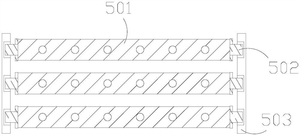
[0034] The lower cartridge 55 includes a roller body 501, a shaft 502, a side fixation plate 503, which is interposed inside the roller 501, and the rotary shaft 502 is connected to the side fixation plate 503.

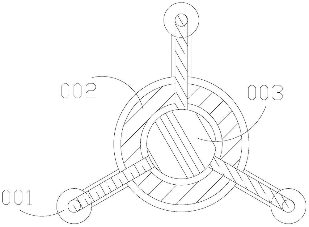
[0035] The roller 501 includes an extension 001, a clip 002, a medium column 003, and the clip 1002 is mounted between the two extensions 001, the clip 002 to the outer surface of the medium column 003, the The extension 001 is provided wi...

Embodiment 2

[0042] Append Figure 7 Adherent Figure 9 Down:

[0043] Wherein, the gluing ball E01 includes an outer gelatin layer 111, an inner empty groove 112, which is embedded inside the outer gelatin layer 111, the outer glue layer 111, made of rubber material, the inner air tank 112 is a vacant structure, and the inner space groove 112 is in force, and the internal space will be extruded.

[0044] Wherein, the inner empty groove 112 includes an extension body M01, an inner groove M02, a block M03, and the block M03 is mounted inside the inner groove M02, the inner groove M02 first end and the extension body M01, said The stretch M01 is provided with two, and when the bodies M01 are extruded in the engagement portion, when the gas is extruded around the body, the active action is expanded, allowing the gas to stretch space, the card When the block M03 is bent in the outer layer, it acts as a limitation.

[0045] Wherein, the extension M01 includes an arc strip S01, a inner clip S02, a str...


PUM


Abstract

The invention discloses a steel pipe discharging roller assembly line which structurally comprises a control box, a supporting rack, a treatment box, a roller belt and a discharge barrel, wherein the roller is mounted on the top of the control box and is connected, the supporting rack is vertically welded to the bottom of the treatment box, the roller belt is located in the treatment box and is movably connected. When a steel pipe is placed on the roller to be transported in a rolling manner, when the steel pipe is in contact with an arc clamping surface, an outer wrap will drag a pull stripe I to bend. In the process that the outer wrap layer is bended, when the steel pipe rolls to discharge, an intercepting and buffering role is played to prevent quick rolling collision. An outer glue layer will carry out an outer force to an empty slot. The internal clamping strip is assistant with a pull range of the arc stripe to bear contact of an external force to extend the stress, thereby playing a limiting and fixing role. In the process that the steel pipe is pocketed, the pocketed part deforms along with the surface of the steel pipe, such that is is auxiliary to attach a fixed force to the steel pipe.

Description

Technical field [0001] The present invention belongs to the field of roller pipelines, and more particularly, it relates to a steel pipe lower cylinder pipeline. Background technique [0002] In the process of adding, the steel pipe needs to be treated by a multi-way step. After the process is processed, the steel pipe is delivered to the next step by the drum pipeline, and each process is processed by the steel pipe one by one. The steel pipe is placed in a corresponding slot, auxiliary overall flow to the steel pipe. [0003] Based on the above-described invention, it has been found that the existing steel pipe fuel tube is mainly in the following shortcomings, such as: [0004] When the steel pipe is in the process of the lower plate, it is easy to add the helper to the tilt of the slope, so that the rapid impact is downward, thereby impacts the steel pipe completed by the front end pad, causing the position of the steel pipe to incline, when it enters a step It is difficult t...

Claims


Application Information

Patent Timeline
IPC IPC(8): B65G47/74B65G13/00B65G39/02
CPCB65G13/00B65G39/02B65G47/74B65G2201/0276
Inventor 何超伟
Owner 何超伟
Why Eureka
Try Eureka