
Rotary tillage soil turning plough

A technology for turning plows and plow holders, which is applied to plows, shovels, agricultural machinery, etc., and can solve problems such as vibration of plowshares

Pending Publication Date: 2021-04-20
何晓静
View PDF0 Cites 0 Cited by
  • Summary
  • Abstract
  • Description
  • Claims
  • Application Information

AI Technical Summary

Problems solved by technology

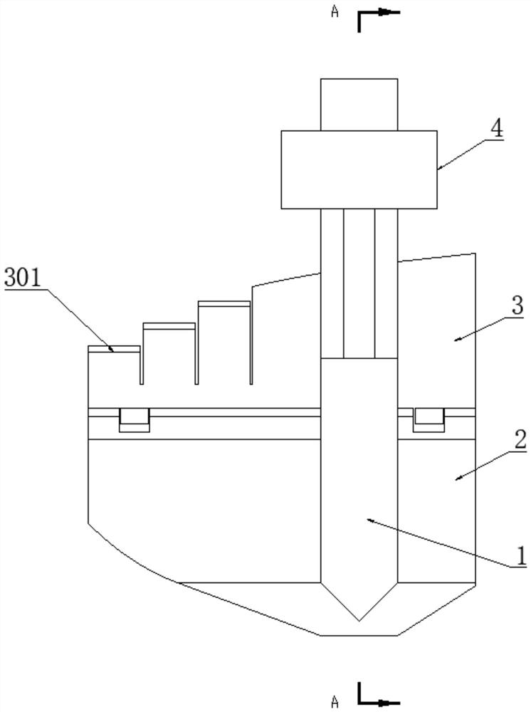
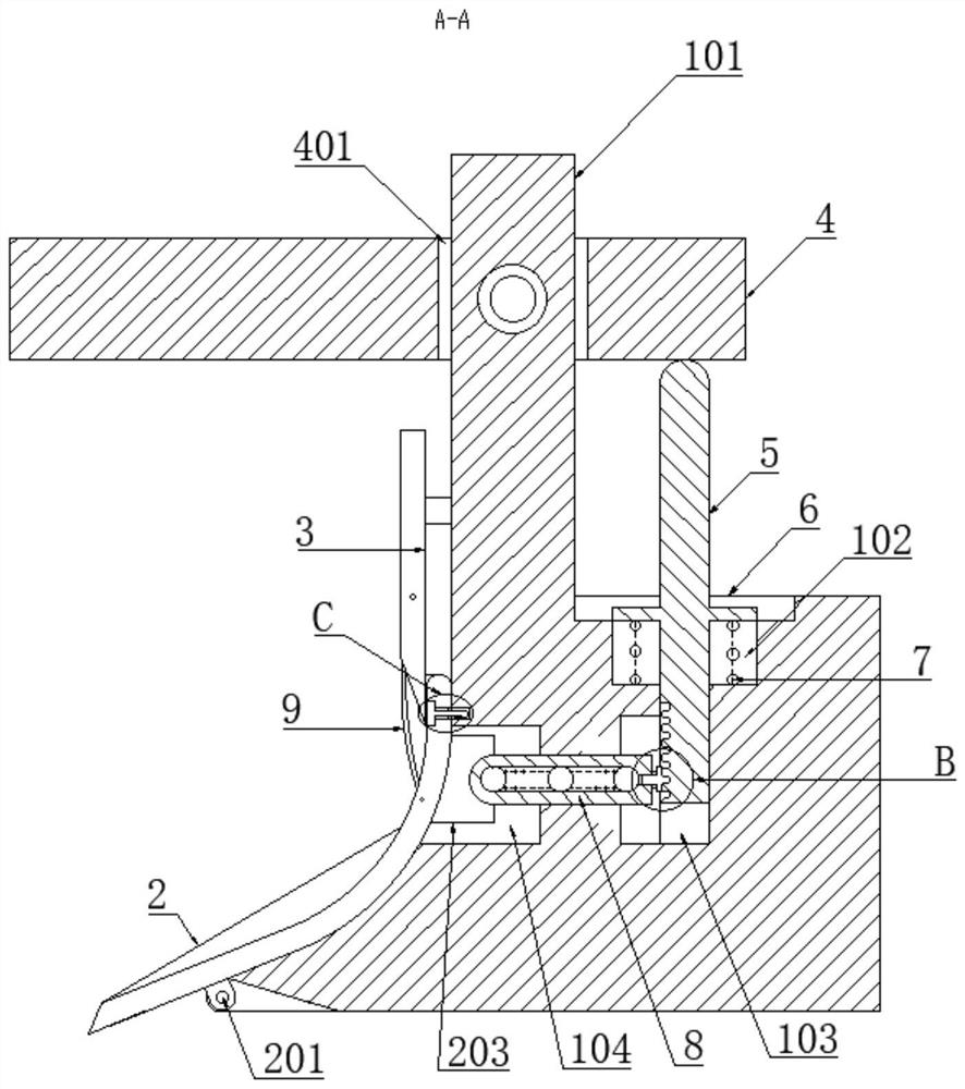
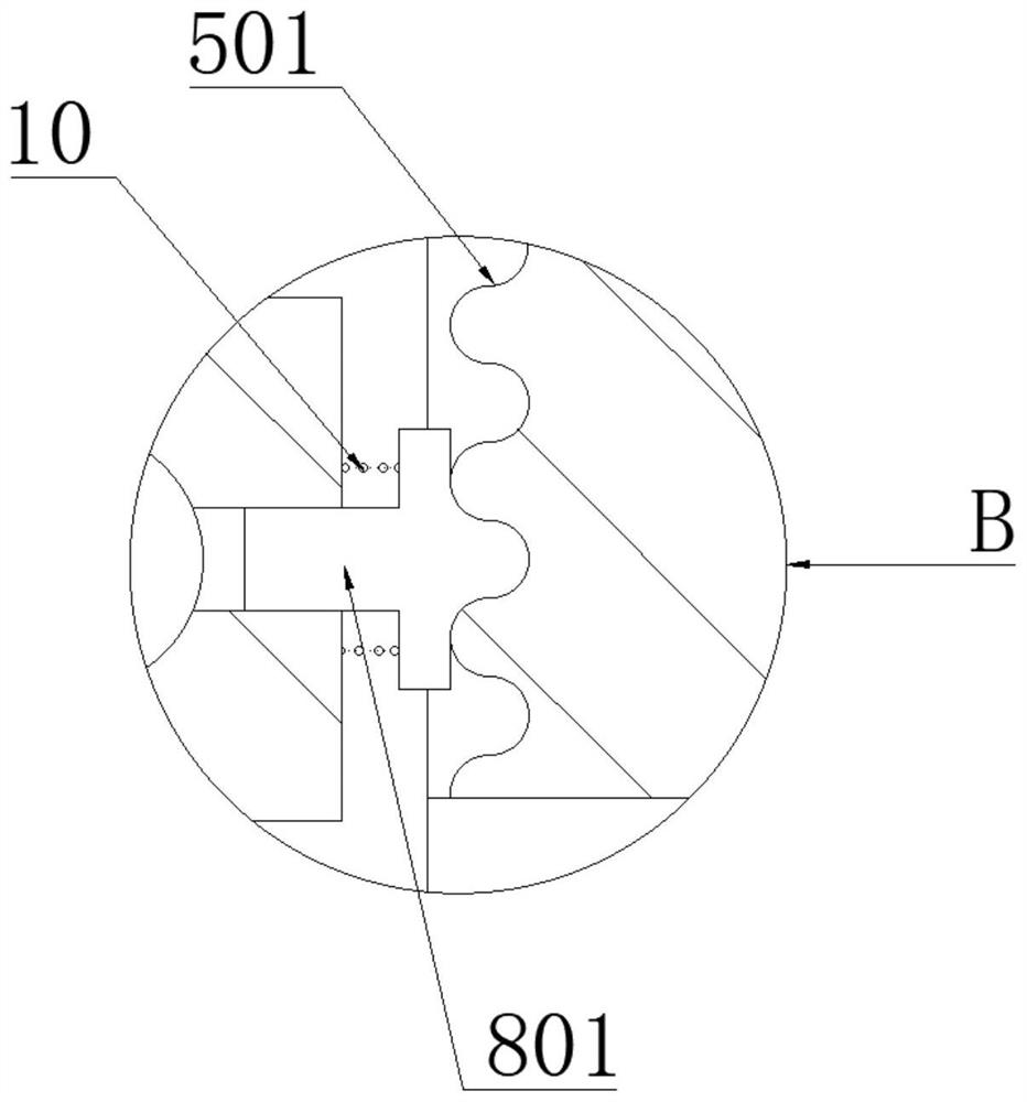
[0003] The purpose of the present invention is to provide a rotary tillage plow, through the movement of the roller of the movable rod along the corrugated surface, the movable rod can reciprocate in the horizontal direction, complete multiple impacts on the sphere, cause the plow share to vibrate, and realize the reciprocating motion of the movable rod on the plow share. The attached dry soil is cleaned, which solves the related problems raised in the background technology

Method used


Image

  • Rotary tillage soil turning plough
  • Rotary tillage soil turning plough
  • Rotary tillage soil turning plough

Examples


Embodiment Construction

[0035] The following will clearly and completely describe the technical solutions in the embodiments of the present invention with reference to the accompanying drawings in the embodiments of the present invention. Obviously, the described embodiments are only some, not all, embodiments of the present invention. Based on the embodiments of the present invention, all other embodiments obtained by persons of ordinary skill in the art without creative efforts fall within the protection scope of the present invention.

[0036] In describing the present invention, it is to be understood that the terms "opening", "upper", "lower", "thickness", "top", "middle", "length", "inner", "surrounding" etc. Indicating orientation or positional relationship is only for the convenience of describing the present invention and simplifying the description, and does not indicate or imply that the components or elements referred to must have a specific orientation, be constructed and operated in a sp...


PUM


Abstract

The invention discloses a rotary tillage soil turning plough, and relates to the technical field of agricultural machinery. The plough comprises a plough support, a plough share is movably installed at the bottom end of the plough support, a coulter is movably connected to the plough share, and the coulter is connected with the side face of the plough support through an installation base; a telescopic ejector rod is installed in a first groove body, one end of the ejector rod stretches into a second groove body, and the other end of the ejector rod makes contact with a plough frame; an impact part is installed in a communicating channel of the second groove body and a third groove body, one end of the impact part is installed in cooperation with one end of the ejector rod, an impacted part is arranged on the back face of the plough share, and the impacted part abuts against the other end of the impact part; and a stand column is vertically arranged on the plough support, and the end of the stand column extends into a slotted hole formed in the plough frame and is rotationally installed in the slotted hole through a pin shaft penetrating through the stand column. According to the rotary tillage soil turning plough, a roller of a movable rod moves along a corrugated surface, so that the movable rod reciprocates in the horizontal direction, a ball is impacted for multiple times, the plough share vibrates, and dry soil attached to the plough share is cleaned.

Description

technical field [0001] The invention belongs to the technical field of agricultural machinery, in particular to a rotary plow for plowing soil. Background technique [0002] Agricultural machinery refers to various machinery used in crop planting and animal husbandry production, as well as in the primary processing and handling of agricultural and animal products. Agricultural machinery includes agricultural power machinery, farmland construction machinery, soil tillage machinery, planting and fertilization machinery, plant protection machinery, farmland drainage and irrigation machinery, crop harvesting machinery, agricultural product processing machinery, animal husbandry machinery and agricultural transportation machinery, etc. A plow, a tool commonly used to turn soil, consists of a heavy blade at the end of a beam. It is usually attached to a group of livestock or a motor vehicle that draws it, but it is also human-powered and is used to break up clods and create furro...

Claims


Application Information

Patent Timeline
Patent Type & Authority Applications(China)
IPC IPC(8): A01B49/02A01B71/08
Inventor 何晓静
Owner 何晓静
Learn More