Traction tension machine for polyester staple fiber processing

A technology of polyester staple fiber and tension machine, which is applied in the field of tension machine, can solve the problems of increasing the processing cost of users, breaking the polyester staple fiber and reducing the processing efficiency of polyester staple fiber.

Pending Publication Date: 2021-06-04
宿迁雪创高纤有限公司
View PDF0 Cites 0 Cited by
  • Summary
  • Abstract
  • Description
  • Claims
  • Application Information

AI Technical Summary

Problems solved by technology

[0003] The stretching machine in the prior art is extremely inconvenient to operate when performing tension processing on polyester staple fibers. Due to the short length and size of polyester staple fibers, the stretching machine in the prior art can easily cause polyeste

Method used


Image

  • Traction tension machine for polyester staple fiber processing
  • Traction tension machine for polyester staple fiber processing
  • Traction tension machine for polyester staple fiber processing

Examples


Embodiment 1

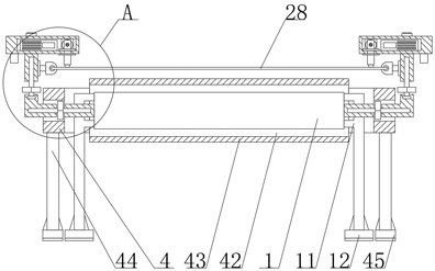
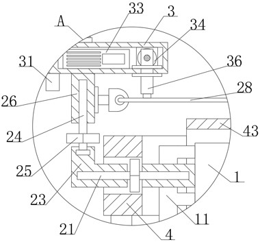
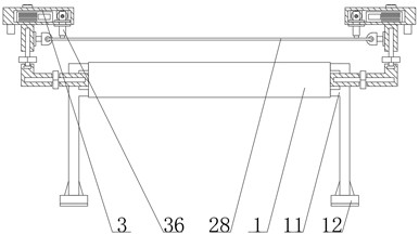
[0026] see Figure 1-6 , the present invention provides a technical solution: a traction tensioner for polyester staple fiber processing, including a mounting plate 1, a fixing piece 2 and a mounting seat 3, and the two sides of the mounting plate 1 near both ends are fixed by bolts Connected with a bracket 11, the mounting plate 1 can be effectively lifted away from the ground through the bracket 11. The middle parts on both sides of the mounting plate 1 are connected to the fixing parts 2 by bolts near the two ends. Screw rods 21 are threadedly inserted on both sides, and a connecting piece 23 is threaded at one end of the periphery of the two screw rods 21. The connecting piece 23 is in an L-shaped structure, and a drive member 22 is welded in the middle of the outer periphery of the screw rods 21. The driving part 22 is used as a rotation adjustment device for the screw rod 21 between the fixing part 2 and the connecting part 23, so that the connecting part 23 and the fixi...

Embodiment 2

[0028] see Figure 1-6, the present invention provides a technical solution: a traction tensioner for polyester staple fiber processing, including a mounting plate 1, a fixing piece 2 and a mounting seat 3, and the two sides of the mounting plate 1 near both ends are fixed by bolts Connected with a bracket 11, the mounting plate 1 can be effectively lifted away from the ground through the bracket 11. The middle parts on both sides of the mounting plate 1 are connected to the fixing parts 2 by bolts near the two ends. Screw rods 21 are threadedly inserted on both sides, and a connecting piece 23 is threaded at one end of the periphery of the two screw rods 21. The connecting piece 23 is in an L-shaped structure, and a drive member 22 is welded in the middle of the outer periphery of the screw rods 21. The driving part 22 is used as a rotation adjustment device for the screw rod 21 between the fixing part 2 and the connecting part 23, so that the connecting part 23 and the fixin...


PUM


Abstract

The invention discloses a traction tension machine for polyester staple fiber processing. The traction tension machine includes a mounting plate, fixing pieces and a mounting base, wherein supports are fixedly connected to positions, close to two ends, of two sides of the mounting plate through bolts, and the fixing pieces are fixedly connected to positions, close to the two ends, of middles of the two sides of the mounting plate through bolts. A motor in the mounting base is started through a switch, so that the motor drives a threaded rod to drive a sliding block to directionally slide in the mounting base, a convex block effectively scrapes a steel wire, tension processing is carried out on polyester staple fibers on a conveying belt through an elastic force action of the steel wire, and therefore, the processing efficiency of the polyester staple fibers is effectively improved; and meanwhile, the fixing pieces are arranged at the positions, close to the two ends, of the middles of the two sides of the mounting plate, so that when a user adjusts the position of a connecting piece through a driving piece, the tension of the steel wire can be effectively adjusted, and then tension processing of different degrees can be conducted on the polyester staple fibers.

Description

technical field [0001] The invention relates to the technical field of tension machines, in particular to a traction tension machine for polyester staple fiber processing. Background technique [0002] Polyester staple fiber is a fiber obtained by spinning polyester (that is, polyethylene terephthalate, PET for short, which is polymerized by PTA and MEG) and then cutting it into tow. PET is in the shape of rice grains or flakes. Various varieties and different colors (usually the main component of beverage bottles we come into contact with is polyester, slice it, and generally go through two main processes of pre-spinning and post-spinning to produce polyester staple fibers. According to different needs, in After spinning, it can be cut into polyester staple fibers of different specifications, generally 4D-22D, and can be divided into two-dimensional and three-dimensional according to its crimp), 75% of which are used for polyester for chemical fibers. According to the requi...

Claims


Application Information

Patent Timeline
IPC IPC(8): D02J1/22
CPCD02J1/22
Inventor 金华东杨德忠周国强吴如春
Owner 宿迁雪创高纤有限公司
Why Eureka
Try Eureka