

Damping mechanism for condensate water machine
A shock-absorbing mechanism and condensate technology, applied in springs/shock absorbers, mechanical equipment, vibration suppression adjustment, etc., can solve problems affecting work accuracy and efficiency, vibration, etc., and achieve the effect of reducing vibration and ensuring inspection accuracy.
- Summary
- Abstract
- Description
- Claims
- Application Information
AI Technical Summary
Problems solved by technology
Method used
Image

Examples
Embodiment 1
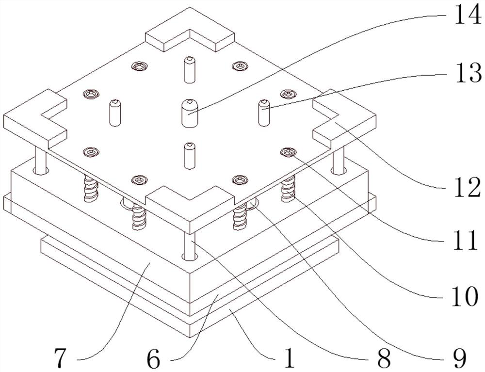
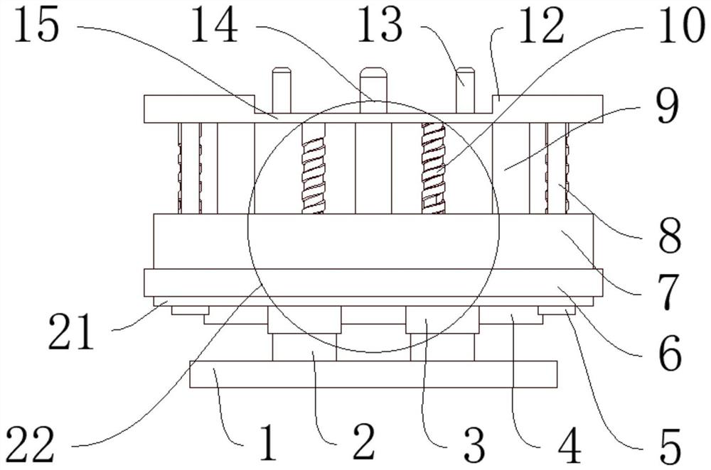
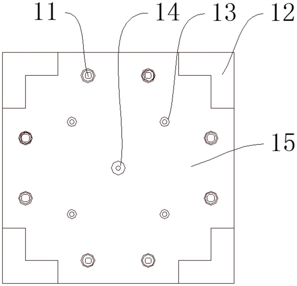
[0038] Such as figure 1 , figure 2 , image 3 , Figure 5 , Figure 6 As shown, a shock absorbing mechanism for a condensate water machine includes a bottom plate 1 and an installation module 15. The installation module 15 includes a positioning plate 12, a first positioning pin 13, and a second positioning pin 14. A shock absorbing mechanism is connected above the bottom plate 1. Module 22, the installation module 15 is connected above the damping module 22, the damping module 22 includes a telescopic column 2, the upper part of the telescopic column 2 is provided with a hydraulic cylinder 3, and one side of the hydraulic cylinder 3 is provided with a first protective cover 19, the first protective cover 19. A second protective cover 20 is provided on the front side, and a fourth protective cover 5 is provided on one side of the second protective cover 20. A metal plate 21 is provided on the upper part of the fourth protective cover 5, and a rubber shock absorbing pad 7 i...
Embodiment 2
[0041] Such as figure 1 , figure 2 , image 3 , Figure 4 , Figure 5 , Figure 6As shown, on the basis of Embodiment 1: the damping module 22 also includes a spring sleeve 9, the upper end of the spring sleeve 9 is fixedly connected with the positioning plate 12, the lower end of the spring sleeve 9 is slidingly connected with the rubber shock absorbing pad 7, and the spring sleeve A damping spring 16 is provided inside the tube 9, a connecting column 17 is provided inside the damping spring 16, a third protective cover 4 is provided on one side of the first protective cover 19, and a third positioning pin 8 is provided on one side of the spring sleeve 9. The bottom of the third positioning pin 8 is provided with a positioning tube 18, one side of the positioning plate 12 is provided with a first positioning pin 13, and a second positioning pin 14 is arranged between the first positioning pins 13, and the first positioning pin 13 is welded to the installation module 15 ...
PUM
 Abstract
Description
Claims
Application Information