Al technical title is built by PatSnap Al team. It summarizes the technical point description of the patent document.
A protection device and shock absorber technology, applied in the direction of springs/shock absorbers, vehicle parts, vehicle springs, etc., can solve the problems such as the decline of the shock absorber's vibration damping performance, affecting the vibration damping performance, and only replacing it, so as to avoid the Compression state, blast prevention, and compression avoidance effects
Pending Publication Date: 2021-06-04
CHANGSHU INSTITUTE OF TECHNOLOGY
View PDF0 Cites 0 Cited by
Summary
Abstract
Description
Claims
Application Information
AI Technical Summary
This helps you quickly interpret patents by identifying the three key elements:
Problems solved by technology
Method used
Benefits of technology
Problems solved by technology
[0003] However, car owners usually observe obvious places, such as observing whether the tires are abnormal. When the car is parked and non-driving for a long time, the spring of the shock absorber will be in a long time due to the self-gravity of the car. In the compressed state, over time, the damping performance of the shock absorber will be reduced, which will affect the comfort of the vehicle when driving
Although the aforementioned factors are easily overlooked by people, objectively, the spring on the shock absorber is in a compressed state for a long time, which affects its damping performance, and can only be replaced in severe cases.
Method used
Image
Click on the blue label to locate the original text in one second.
Reading with bidirectional positioning of images and text.
Examples
Embodiment Construction
[0016] The following will clearly and completely describe the technical solutions in the embodiments of the present invention with reference to the accompanying drawings in the embodiments of the present invention. Obviously, the described embodiments are only some, not all, embodiments of the present invention. Based on the embodiments of the present invention, all other embodiments obtained by persons of ordinary skill in the art without making creative efforts belong to the protection scope of the present invention.
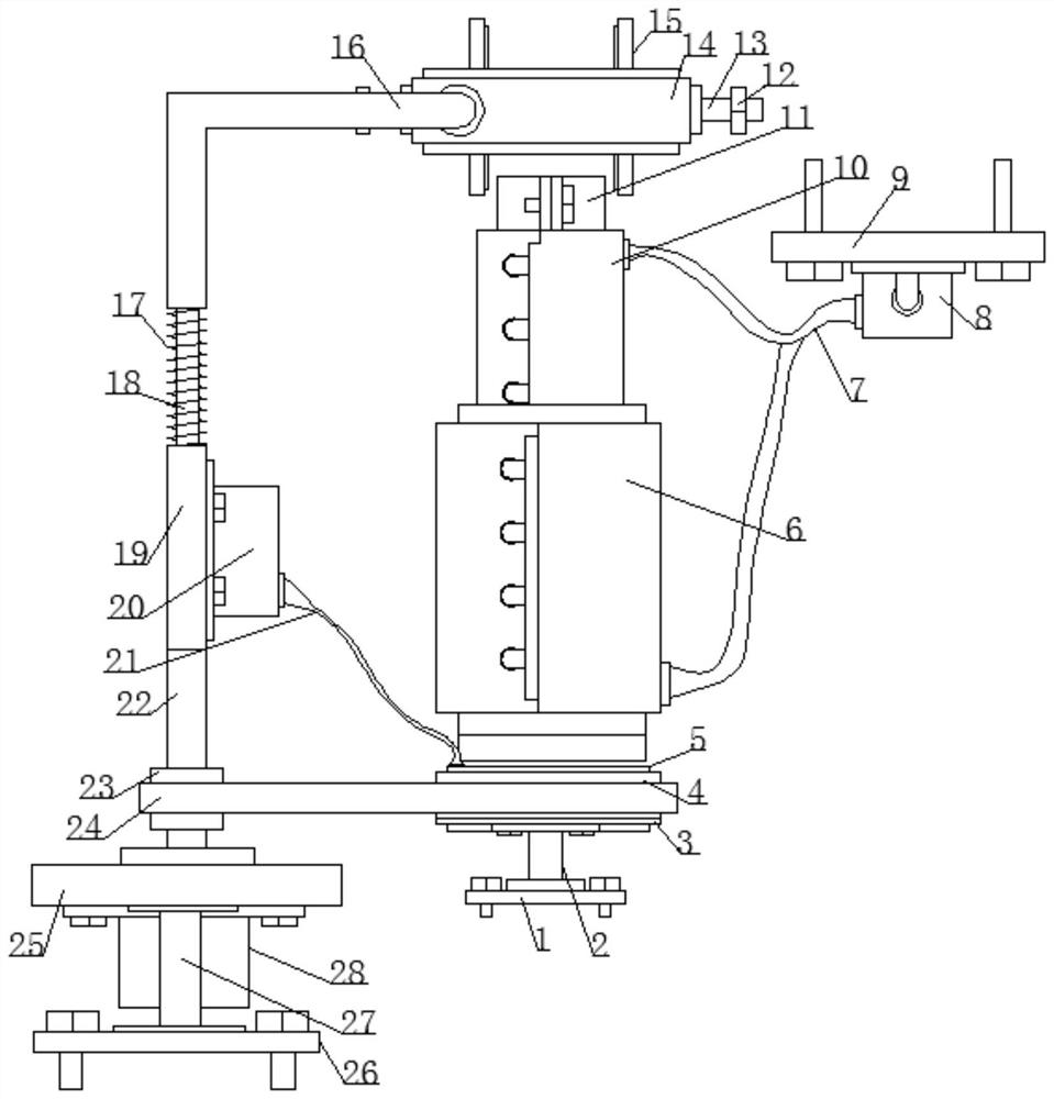
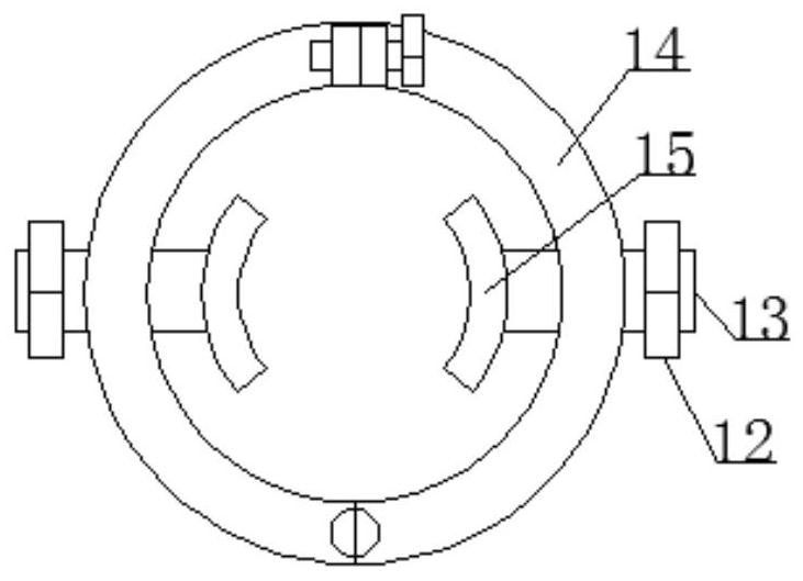
[0017] see Figure 1-2 , the present invention provides a technical solution:
[0018] An automobile shock absorber protection device, comprising a first mounting plate 1, a second mounting plate 9 and a third mounting plate 26, the upper side of the first mounting plate 1 is fixed with a first support rod 2, the first A top plate 3 is fixedly installed on the top of the support rod 2, a first swivel 4 is installed on the upper side of the top plate 3, a firs...
PUM
Abstract
The invention discloses an automobile shock absorber protection device. The device comprises a first installation plate, a second installation plate and a third installation plate, a first supporting rod is arranged on the first installation plate, a top plate is arranged at the top end of the first supporting rod, a first rotating ring is installed at the upper side of the top plate, a first air bag is arranged in the first rotating ring, a clamping pipe is arranged above the first rotating ring, and a third air bag and a second air bag are arranged above and below the clamping pipe. A first air pump is arranged on the lower surface of the second installation plate, first guide pipes are arranged between the first air pump and the second air bag and between the first air pump and the third air bag, a second supporting rod is arranged on the third installation plate, a fixing plate is arranged at the top end of the second supporting rod, a motor is arranged on the lower surface of the fixing plate, a rotating shaft is arranged at the upper side of the motor, a second rotating ring is arranged on the surface of the rotating shaft, a belt is arranged between the second rotating ring and the first rotating ring, a second sliding pipe is arranged at the top end of the rotating shaft, and a second air pump is arranged at the right side of the second sliding pipe. A second guide pipe is arranged between the second air pump and the first air bag, a spiral spring is arranged at the upper end of the second sliding pipe, a sliding rod is arranged in the spiral spring, the spiral spring is provided with a first sliding pipe, a lantern ring is arranged outside the first sliding pipe, screws are arranged on the two side walls of the lantern ring, clamping plates are arranged in the screws, and the screws are sleeved with nuts.
Description
technical field [0001] The invention belongs to the field of automobiles, and in particular relates to an automobile shock absorber protection device. Background technique [0002] In the suspension system, due to the shock of the elastic element, vibration is generated. In order to improve the ride comfort of the car, that is, the stability, a shock absorber is installed in parallel with the elastic element in the suspension. The working principle of the shock absorber is: when the frame (or body) and the axle are vibrated and there is relative movement, the piston in the shock absorber moves up and down, and the oil in the shock absorber chamber repeatedly passes through different chambers. The pores flow into another cavity. [0003] However, car owners usually observe obvious places, such as observing whether the tires are abnormal. When the car is parked and non-driving for a long time, the spring of the shock absorber will be in a long time due to the self-gravity of ...
Claims
Application Information
Patent Timeline
Application Date:The date an application was filed.
Publication Date:The date a patent or application was officially published.
First Publication Date:The earliest publication date of a patent with the same application number.
Issue Date:Publication date of the patent grant document.
PCT Entry Date:The Entry date of PCT National Phase.
Estimated Expiry Date:The statutory expiry date of a patent right according to the Patent Law, and it is the longest term of protection that the patent right can achieve without the termination of the patent right due to other reasons(Term extension factor has been taken into account ).
Invalid Date:Actual expiry date is based on effective date or publication date of legal transaction data of invalid patent.