
Test system for automatically calibrating power factor of semi-active CWDM module

A technology of module power and testing system, which is applied in the direction of using electric radiation detectors for photometry, etc., and can solve the problems of inability to lay optical cables, expensive fees, and expensive household registration.

Pending Publication Date: 2021-06-04
安徽共芯光子科技有限公司
View PDF0 Cites 0 Cited by
  • Summary
  • Abstract
  • Description
  • Claims
  • Application Information

AI Technical Summary

Problems solved by technology

[0002] With the shortage of pipeline resources in national strategic cities, the scenarios for laying optical cables are gradually limited; in areas where optical cables are scarce, there will be no pipeline resources or scenarios where optical cables cannot be laid; Long time and large investment; due to municipal coordination, pipeline construction, and pipeline laying, the time period for optical cable scheduling is long, the communication cost is high, and the cost of optical cable laying is higher than the cost of fronthaul equipment; Practical problems of difficult and expensive household registration; at present, indoor distribution construction needs to be communicated with the customer's property department, and there are problems such as long time, slow opening of the station, and expensive fees; in this case, the CWDM module with OLP function can be very good It solves the above-mentioned problems of 5G network, and solves the problems of large number of fronthaul network laying and difficult maintenance in the later stage. It is also the most effective solution for fronthaul network that comprehensively considers fiber saving, low cost and controllability.
[0003] However, the existing CWDM module power factor calibration is still at the stage of manual calibration. Manual calibration takes a long time, has low efficiency and poor accuracy, so it is necessary to improve it.

Method used


Image

  • Test system for automatically calibrating power factor of semi-active CWDM module

Examples


Embodiment Construction

[0064] The following will clearly and completely describe the technical solutions in the embodiments of the present invention with reference to the accompanying drawings in the embodiments of the present invention. Obviously, the described embodiments are only some, not all, embodiments of the present invention. Based on the embodiments of the present invention, all other embodiments obtained by persons of ordinary skill in the art without making creative efforts belong to the protection scope of the present invention.

[0065] In the description of the invention, it should be noted that the terms "upper", "lower", "inner", "outer", "front end", "rear end", "both ends", "one end", "another end" etc. The indicated orientation or positional relationship is based on the orientation or positional relationship shown in the drawings, and is only for the convenience of describing the invention and simplifying the description, rather than indicating or implying that the referred device...


PUM


Abstract

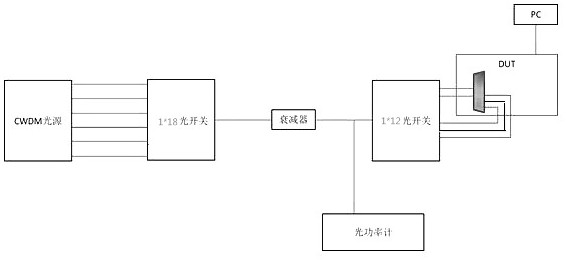
The invention discloses a test system for automatically calibrating a power factor of a semi-active CWDM module, which comprises the following steps: firstly, issuing an instruction through software to ensure that a PRI path is conducted, and turning on all 18 paths of light sources of a CWDM light source module, wherein the method comprises the specific operation steps that the optical power of an optical power channel 1 is read through an optical power meter, and the output optical power W1 of a 1*12 optical switch channel 1 is calculated according to the splitting ratio of an optical splitter and the insertion loss of a 1*12 optical switch; inputting an instruction through a serial port of the PC, and obtaining ADC voltage values Vp1 and V1 of the DUT according to an ADC reading position and register position map of each wave band in the PC; and automatically calibrating the power factor, wherein manual calibration is not needed, and the method has the advantages of being efficient, rapid, easy to operate, high in passing rate and the like, and therefore, the production efficiency is greatly improved, and the calibration time is shortened.

Description

technical field [0001] The invention relates to the technical field of semi-active CWDM module power factor, in particular to a test system for automatically calibrating the power factor of a semi-active CWDM module. Background technique [0002] With the shortage of pipeline resources in national strategic cities, the scenarios for laying optical cables are gradually limited; in areas where optical cables are scarce, there will be no pipeline resources or scenarios where optical cables cannot be laid; Long time and large investment; due to municipal coordination, pipeline construction, and pipeline laying, the time period for optical cable scheduling is long, the communication cost is high, and the cost of optical cable laying is higher than the cost of fronthaul equipment; Practical problems of difficult and expensive household registration; at present, indoor distribution construction needs to be communicated with the customer's property department, and there are problems...

Claims


Application Information

Patent Timeline
Patent Type & Authority Applications(China)
IPC IPC(8): G01J1/42
CPCG01J1/42
Inventor 李怀胜许明王保东穆安容张宇航王继宏卢义鑫
Owner 安徽共芯光子科技有限公司
Learn More