
Automatic frequency correction method and system

An automatic frequency correction and frequency correction technology, applied in transmission systems, digital transmission systems, baseband system components, etc., can solve problems such as frequency offset, frequency drift, and inability to demodulate signals at both ends of the transceiver, and achieve frequency Calibration, intelligent frequency correction, cost reduction effect

Active Publication Date: 2014-03-12
FUJIAN SUNNADA TECH CO LTD
View PDF4 Cites 15 Cited by
  • Summary
  • Abstract
  • Description
  • Claims
  • Application Information

AI Technical Summary

Problems solved by technology

[0003] In order to achieve synchronization, conventional digital wireless stations use high-precision crystal oscillators at both ends of the transceiver, which are expensive. At the same time, frequency drift will occur after long-term use, and frequency deviation will occur at both ends of the transceiver, which requires regular manual frequency adjustment. Correction, for some wireless stations using cheap crystal oscillators, their stability will decrease due to a long time, which will add a frequency offset to the received data, which will cause frequency offsets in the near and far-end system frequencies, and the far-end will not Demodulation of the signal at the near end, so that the near and far ends cannot be synchronized

Method used


Image

  • Automatic frequency correction method and system
  • Automatic frequency correction method and system
  • Automatic frequency correction method and system

Examples


Embodiment Construction

[0030] In order to describe the technical content, structural features, achieved goals and effects of the present invention in detail, the following will be described in detail in conjunction with the embodiments and accompanying drawings.

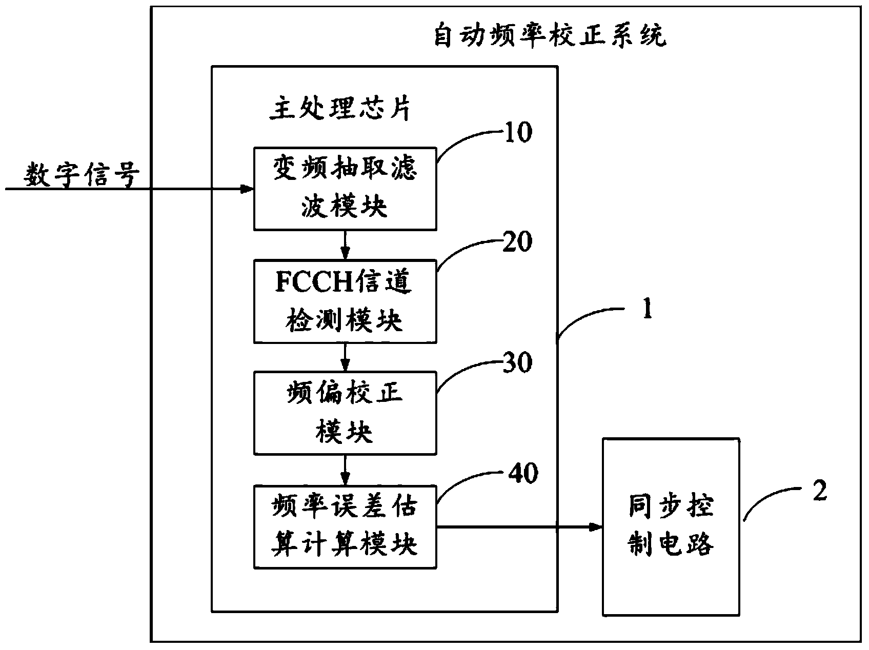
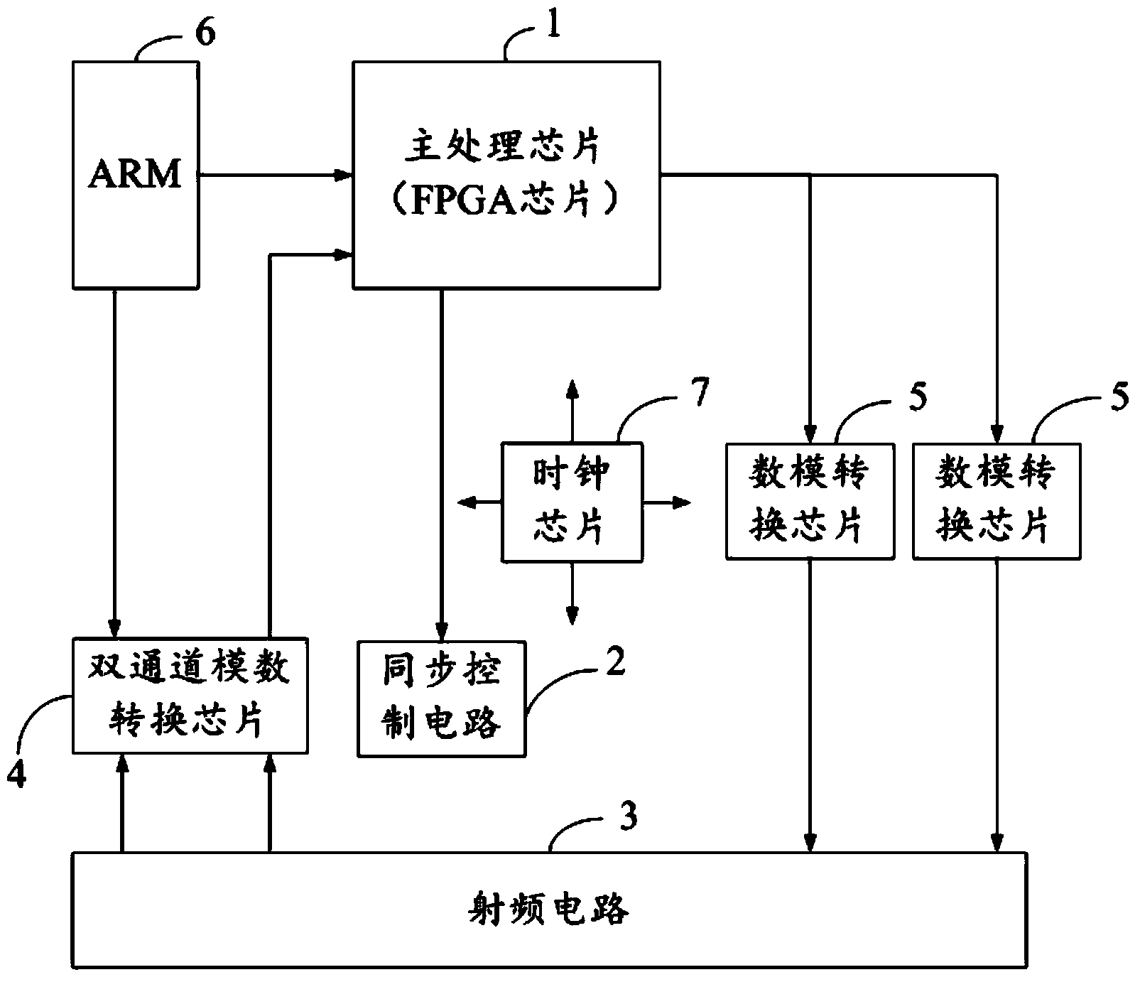
[0031] In the GSM system, in the downlink process, the signal of the base station passes through the near-end digital wireless station, the near-end digital wireless station transmits to the far-end digital wireless station through radio frequency, and the far-end digital wireless station transmits the downlink signal to the mobile station through radio frequency. Station reception, uplink and vice versa. Among them, the mobile station and the base station must be correctly synchronized to communicate normally, and the prerequisite for synchronization is to capture the frequency correction signal (FCCH).

[0032] The present invention mainly captures the downlink FCCH of the base station, estimates the frequency offset of the signal, and a...


PUM


Abstract

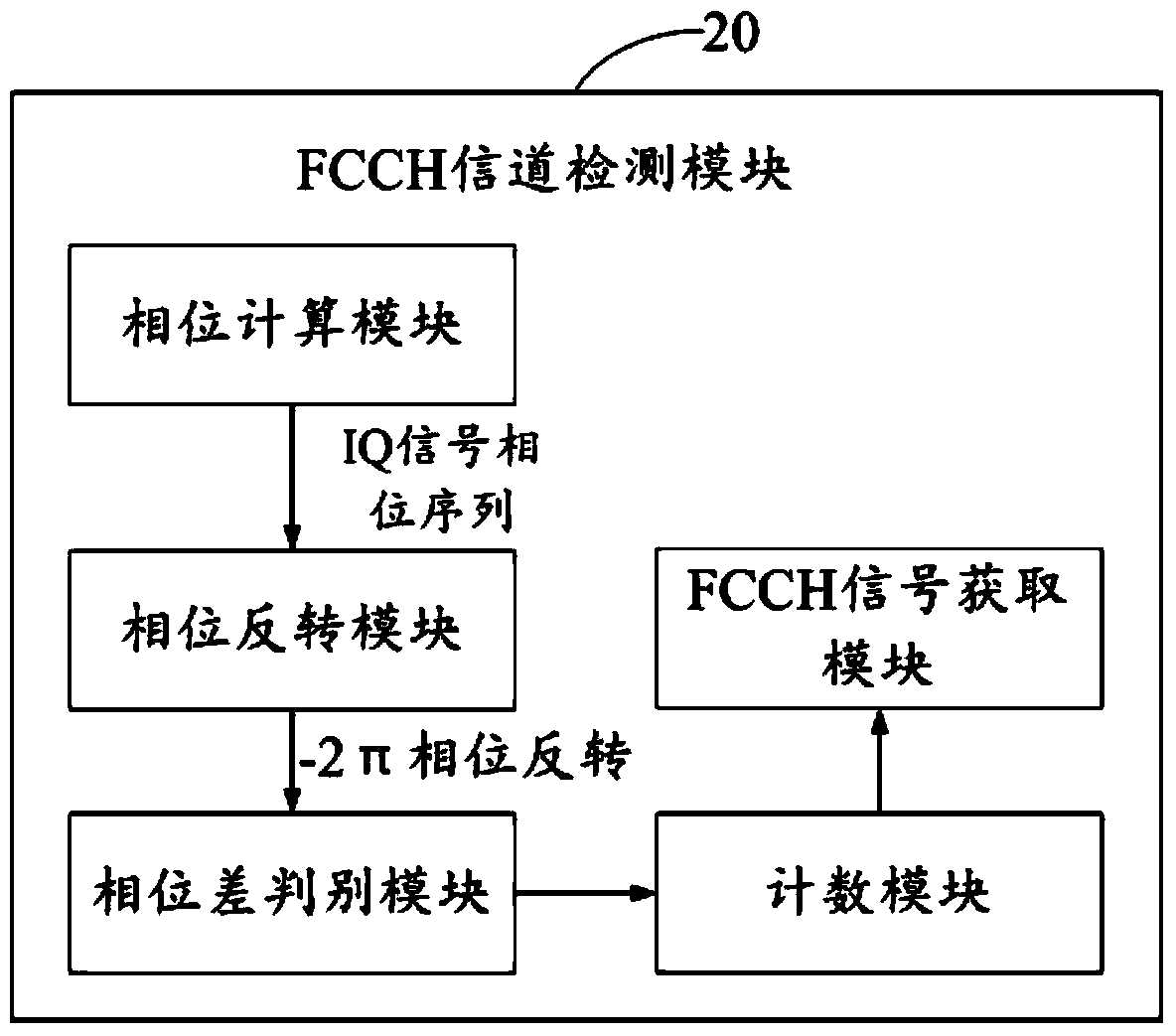
The invention discloses an automatic frequency correction method which comprises the following steps: S1. carrying out down-conversion decimation filtration on a received and sampled digital signal of with the frequency point is 15.36 MHz and the data rate is 61.44 MHz to obtain a 269.473K GSM (Global System for Mobile Communication) signal; S2 carrying out FCCH (frequency correction channel) detection on the GSM signal to acquire an FCCH signal; S3. fitting FCCH data into a linear slope, and demodulating to obtain an output slope; S4. comparing the output slope with the ideal slope to calculate a slope deviation value so as to correspondingly obtain a frequency deviation value; acquiring input data of a synchronous control circuit according to the slope deviation value through a look-up table, and allocating the input data to the synchronous control circuit; and S5. generating an output voltage by the synchronous control circuit according to the input data to control the crystal oscillator clock pulse (CP), thereby implementing the frequency correction. The invention also discloses an automatic frequency correction system.

Description

technical field [0001] The invention relates to an automatic frequency correction method and system. Background technique [0002] In a wireless communication system, in order to ensure normal communication between transceiver wireless stations, it is necessary to ensure that the frequency of the frequency source signal at the receiving end is consistent with the frequency of the frequency source signal at the transmitting end, so as to achieve the purpose of synchronization and correctly demodulate the signal transmitted by the user. [0003] In order to achieve synchronization, conventional digital wireless stations use high-precision crystal oscillators at both ends of the transceiver, which are expensive. At the same time, frequency drift will occur after long-term use, and frequency deviation will occur at both ends of the transceiver, which requires regular manual frequency adjustment. Correction, for some wireless stations using cheap crystal oscillators, their stabil...

Claims


Application Information

Patent Timeline
Patent Type & Authority Applications(China)
IPC IPC(8): H04L25/03H04L7/00
Inventor 黄海峰张祖良
Owner FUJIAN SUNNADA TECH CO LTD
Learn More