Wire tightening device for low-voltage bundled wire installation

A technology for bundled wires and installation is applied in the field of wire tightening devices for low-voltage bundled wire installation, which can solve the problems of inconvenient wire tightening construction, waste of time and energy, cumbersome operation process, etc., so as to avoid off-line phenomenon and reduce operation time. , the effect of reducing labor intensity

Active Publication Date: 2021-06-04
STATE GRID ZHEJIANG TONGLU POWER SUPPLY +1
View PDF9 Cites 3 Cited by
  • Summary
  • Abstract
  • Description
  • Claims
  • Application Information

AI Technical Summary

Problems solved by technology

[0002] In recent years, in power grid reconstruction projects, bundled cables have been widely used, and bundled cables have also become the main material of the connection, and the most basic construction process for connection during tight wire work. The current construction method is to use two single The clamping device of the card slot and the two wire take-ups are mixed and used alternately. First, use one clamping device to initially tighten the bundled cables. After the bundled cables are tightened due to unbalanced force, they will be twisted and wound. Install the second thread clamp to balance the force, and then slowly adjust the two thread clamps to complete the thread tightening work. This kind of operation process is cumbersome, which brings inconvenience and increases the difficulty of the thread tightening construction. waste of time and energy

Method used


Image

  • Wire tightening device for low-voltage bundled wire installation
  • Wire tightening device for low-voltage bundled wire installation
  • Wire tightening device for low-voltage bundled wire installation

Examples


Embodiment Construction

[0036] In order to explain the overall concept of the present invention more clearly, the following will be described in detail by way of examples in combination with the accompanying drawings.

[0037] It should be noted that many specific details have been set forth in the following description so as to fully understand the present invention, but the present invention can also be implemented in other ways different from those described here, therefore, the protection scope of the present invention is not limited by the following limitations of the specific embodiments disclosed.

[0038] In addition, in the description of the present invention, it should be understood that the terms "center", "upper", "lower", "front", "rear", "left", "right", "vertical", "horizontal" ", "Top", "Bottom", "Inner", "Outer", "Axial", "Radial", "Circumferential" and other indicated orientations or positional relationships are based on the orientations or positional relationships shown in the dra...


PUM


Abstract

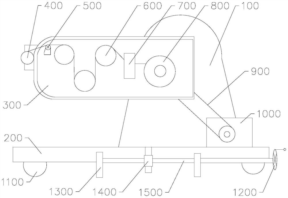
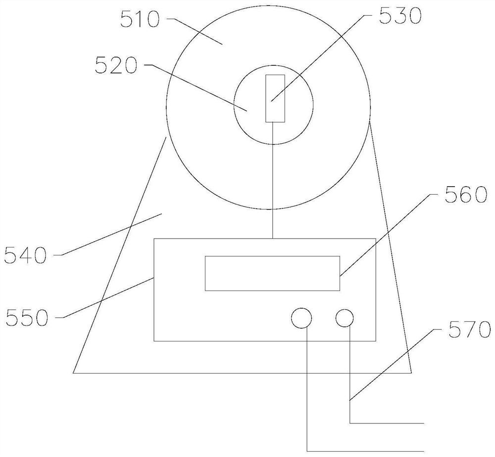
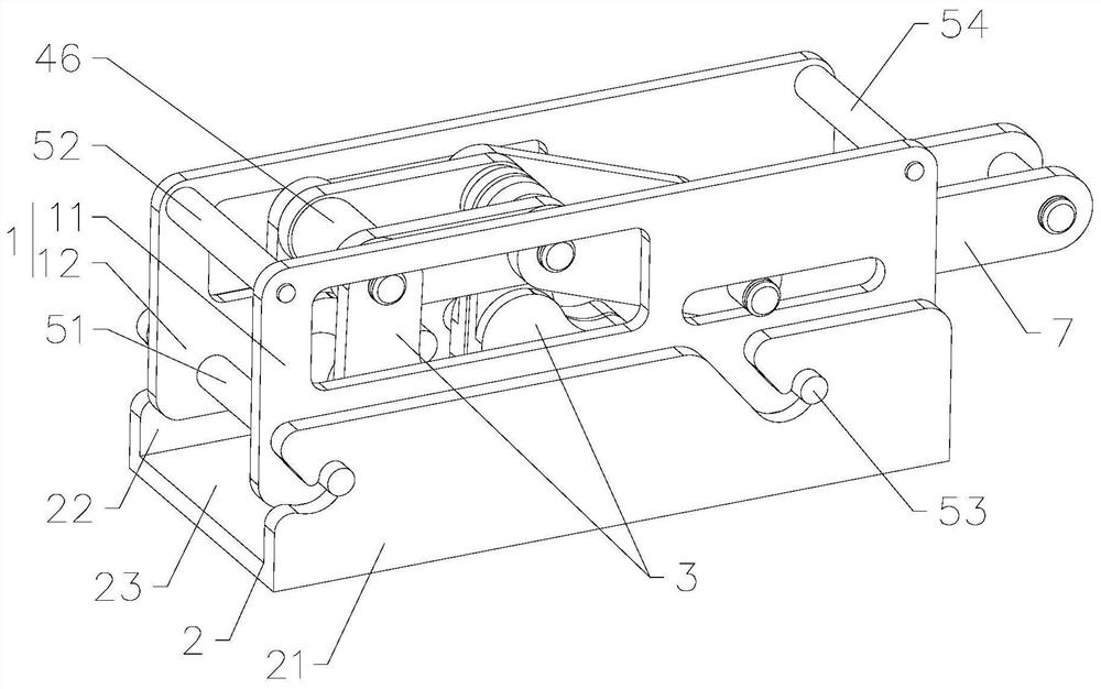
The invention provides a wire tightening device for low-voltage bundled wire installation, which comprises a bracket, a base, a tensioning frame, a wire clamping device, a tension detection device, a pulley block, a non-return device, a winding wheel, a synchronous belt, a driving motor, a moving wheel, a fixed hand wheel, a moving clamping jaw, a fixed clamping jaw and a lead screw, and is characterized in that the wire clamping device comprises a frame plate and a wire pressing assembly; the wire pressing assembly comprises four wire pressing cams, a connecting plate and a pressing handle, every two of the four wire pressing cams are divided into two sets of wire pressing cams, the two sets of wire pressing cams comprise the first set of wire pressing cams and the second set of wire pressing cams, the first set of wire pressing cams and the second set of wire pressing cams are arranged in a front-back spaced mode and the frame plate comprises a bottom frame plate and a side frame plate; the wire pressing assembly is arranged on the side frame plate, and after the side frame plate and the bottom frame plate are installed in place, the four wire pressing cams press and fix the bundled wires placed on the bottom frame plate, so that the wire tightening effect and the operation efficiency of the wire tightening device can be greatly improved, the operation time of operators is shortened, and the labor intensity of the operators is reduced.

Description

technical field [0001] The invention relates to the field of electric power operation equipment, in particular to a wire tightening device for installing low-voltage bundled wires. Background technique [0002] In recent years, in power grid reconstruction projects, bundled cables have been widely used, and bundled cables have also become the main material of the connection, and the most basic construction process for connection during tight line work. The current construction method is to use two single The clamping device of the card slot and the two wire take-up devices are mixed and used alternately. First, use one clamping device to initially tighten the bundled cables. After the bundled cables are tightened, they will be twisted due to unbalanced force. Install the second thread clamp to balance the force, and then slowly adjust the two thread clamps to complete the thread tightening work. This kind of operation process is cumbersome, which brings inconvenience and inc...

Claims


Application Information

Patent Timeline
Patent Type & Authority Applications(China)
IPC IPC(8): H02G1/04H02G1/00
CPCH02G1/04H02G1/00Y02W30/82
Inventor 毕安郭超军詹磊雷超徐榕拥俞凯张岳杨竞谢俊俏段朗朱青峰
Owner STATE GRID ZHEJIANG TONGLU POWER SUPPLY
Why Eureka
Try Eureka