
High-voltage overhead line power cross arm

A high-voltage overhead and line technology, applied in the field of power cross-arms, can solve the problems of heavy manual work, adjusting insulators, increasing the intensity and workload of workers' installation operations, so as to improve work efficiency, reduce work load, and improve stability sexual effect

Active Publication Date: 2021-06-04
STATE GRID JIANGSU ELECTRIC POWER CO LTD NANTONG POWER SUPPLY BRANCH
View PDF3 Cites 1 Cited by
  • Summary
  • Abstract
  • Description
  • Claims
  • Application Information

AI Technical Summary

Problems solved by technology

[0003] The current power cross-arms of high-voltage overhead lines are often assembled and spliced ​​by a single steel structure truss. After assembly and splicing, the power cross-arms of high-voltage overhead lines are mostly fixed structures, and it is difficult to adjust the distance between insulators according to the actual wiring harness specifications. The distance between them keeps a certain safe distance, and the power cross-arm is often operated at high altitude when it is installed and fixed, and the number of support frames that need to be assembled and fixed is large, which increases the work intensity and workload of workers' installation operations, and the electric power The insulators on the cross-arm are generally installed fixedly. When they are damaged and need to be replaced, special disassembly tools are required. The manual work is heavy, and it is difficult to improve the efficiency of disassembly and installation of insulators.

Method used


Image

  • High-voltage overhead line power cross arm
  • High-voltage overhead line power cross arm
  • High-voltage overhead line power cross arm

Examples


Embodiment Construction

[0024] Embodiments of the present invention will be described below with reference to the drawings. In the process, in order to ensure the clarity and convenience of illustration, we may exaggerate the width of the lines or the size of the constituent elements in the diagram.

[0025] In addition, the following terms are defined based on the functions in the present invention, and may be different according to the user's or operator's intention or practice. Therefore, these terms are defined based on the entire content of this specification.

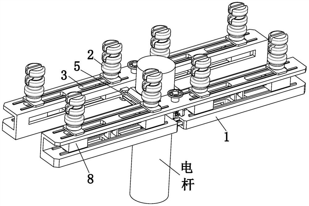
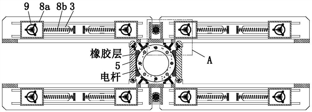
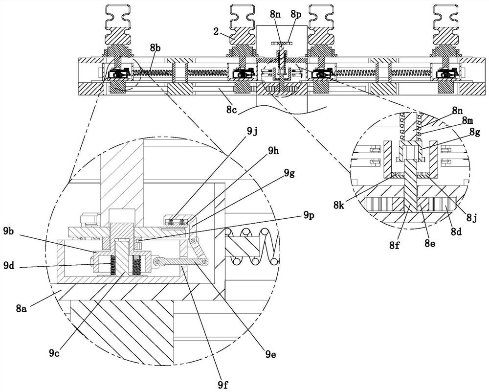
[0026] like Figure 1 to Figure 6As shown, a high-voltage overhead line power cross arm includes a mounting frame 1, an insulator 2, a shifting chute 3, a clamping shaft 4, a clamping rotating rod 5, a clamping slider 6, a clamping spring 7, a displacement Mechanism 8, positioning mechanism 9, support seat 10 and support spring 11, the number of described mounting frame 1 is two, and mounting frame 1 is symmetrically installed on both ...


PUM


Abstract

The invention provides a high-voltage overhead line power cross arm which comprises a mounting frame, an insulator, a shifting sliding groove, a clamping rotating shaft, a clamping rotating rod, a clamping sliding block, a clamping spring, a shifting mechanism, a positioning mechanism, a supporting seat and a supporting spring. The problems that an existing high-voltage overhead line power cross arm is usually formed by assembling and splicing a single steel structure truss, the spacing distance between insulators is difficult to adjust according to the specification of an actually-installed wire harness to keep a certain safe distance, the power cross arm is always in high-altitude operation during installation and fixation, the number of supporting frames needing to be assembled and fixed is large, the work intensity and work amount of installation work of workers are increased, insulators on the electric power cross arm are generally fixedly installed, special disassembly tools are needed when the insulators are damaged and need to be replaced, the manual work amount is large, and the work efficiency of insulator disassembly and installation work is difficult to improve are solved.

Description

technical field [0001] The invention relates to the technical field of electric power cross-arms, in particular to a power cross-arm for high-voltage overhead lines. Background technique [0002] The power cross arm is an important part of the pole tower. The power cross arm is an angle iron fixed horizontally on the top of the utility pole. There is a porcelain bottle on it, which is used to install insulators and fittings to support the wires and lightning conductors and keep them in accordance with regulations. A certain safe distance. [0003] The current power cross-arms of high-voltage overhead lines are often assembled and spliced ​​by a single steel structure truss. After assembly and splicing, the power cross-arms of high-voltage overhead lines are mostly fixed structures, and it is difficult to adjust the distance between insulators according to the actual wiring harness specifications. The distance between them keeps a certain safe distance, and the power cross-a...

Claims


Application Information

Patent Timeline
IPC IPC(8): H02G7/00H02G7/20H02G7/05E04H12/24E04H12/10E04H12/18
CPCH02G7/00H02G7/20H02G7/05E04H12/24E04H12/10E04H12/18
Inventor 陆同玉韩晓伟
Owner STATE GRID JIANGSU ELECTRIC POWER CO LTD NANTONG POWER SUPPLY BRANCH
Learn More