Clamping protection circuit with adjustable voltage

A voltage regulation circuit and clamping protection technology, applied in electrical components, output power conversion devices, conversion equipment without intermediate conversion to AC, etc. effect of work

Active Publication Date: 2021-06-04
58TH RES INST OF CETC
View PDF5 Cites 1 Cited by
  • Summary
  • Abstract
  • Description
  • Claims
  • Application Information

AI Technical Summary

Problems solved by technology

[0005] The traditional simple way is to use the Zener tube to directly clamp, such as figure 2 As shown, DZ0 and DZ1 are used to clamp the VG voltage. Although this method is simple in structure, it brings two problems. The clamping voltage of the first Zener tube will vary according to different process factories, and the clamping voltage of the second Zener tube The voltage is basically around 5.5V, and the adjustable clamping voltage cannot be realized. Therefore, a voltage-adjustable clamping protection circuit is proposed.

Method used


Image

  • Clamping protection circuit with adjustable voltage
  • Clamping protection circuit with adjustable voltage
  • Clamping protection circuit with adjustable voltage

Examples


Embodiment Construction

[0025] The following will clearly and completely describe the technical solutions in the embodiments of the present invention with reference to the accompanying drawings in the embodiments of the present invention. Obviously, the described embodiments are only some, not all, embodiments of the present invention. Based on the embodiments of the present invention, all other embodiments obtained by persons of ordinary skill in the art without making creative efforts belong to the protection scope of the present invention.

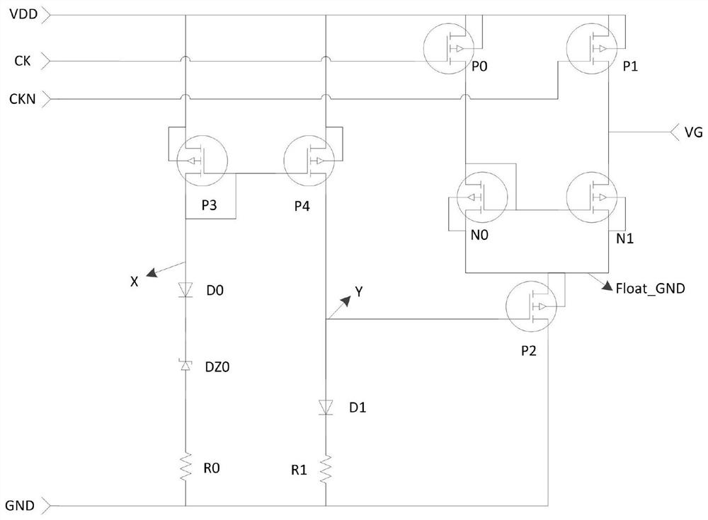
[0026] see image 3 , the present invention provides a technical solution:

[0027] A clamp protection circuit with adjustable voltage, including a voltage regulation circuit and a clamp protection circuit, the voltage regulation circuit and the clamp protection circuit are connected:

[0028] Voltage regulation circuit: used to match the appropriate protection voltage according to the required protection voltage;

[0029] Clamp protection circuit: used to g...


PUM


Abstract

The invention discloses a clamping protection circuit with adjustable voltage, which comprises a voltage regulation circuit and a clamping protection circuit body, the voltage regulation circuit is connected with the clamping protection circuit body, the voltage regulation circuit is used for automatically matching proper protection voltage according to voltage required to be protected and the clamping protection circuit body is used for generating a clamping voltage. The clamping position circuit is used in a charge pump, and can ensure that a gate oxide layer of a PMOS transistor is not broken down mainly when the high-voltage PMOS transistor is driven, so that the charge pump can work normally.

Description

technical field [0001] The invention relates to the technical field of protection circuits, in particular to a clamp protection circuit with adjustable voltage. Background technique [0002] In the prior art, there is usually a group of PMOS and NMOS transistors in the charge pump circuit, such as figure 1 As shown, one group of PMOS and NMOS transistors, that is, P0 and N0, form a charging and discharging circuit of the charge pump capacitor, which is used to determine the lower plate potential of the charge pump capacitor C0; when the PMOS transistor is turned on (the NMOS transistor is turned off) , the lower plate of the capacitor will be charged to the VDD potential; when the NMOS transistor is turned on (the PMOS transistor is turned off), the lower plate of the capacitor will be charged to the GND potential. Under the control of the frequency CK, the charge on the upper plate of the capacitor will also be raised to the required potential, which is the principle of th...

Claims


Application Information

Patent Timeline
Patent Type & Authority Applications(China)
IPC IPC(8): H02M1/32H02M3/07
CPCH02M1/32H02M3/07
Inventor 周海澎
Owner 58TH RES INST OF CETC
Why Eureka
Try Eureka